As of version 2.8.0 of Sentinel VoLTE sticky session replication is supported.
Session Replication means that an existing session is available for processing after a node it was running on has failed. That is, the session is failed over to another node.
The phrase "sticky" refers to the fact that a session is processed on a node (say node 1), until such a time as the node fails. Once the session has failed over, it is then adopted to a new node (say node 2) and then sticks to the new node. Once the original node (node 1) recovers, the failed over session stays stuck to the new node (node 2).
There are several key concepts used to support Sticky Session Replication.
Outline of subsystems involved
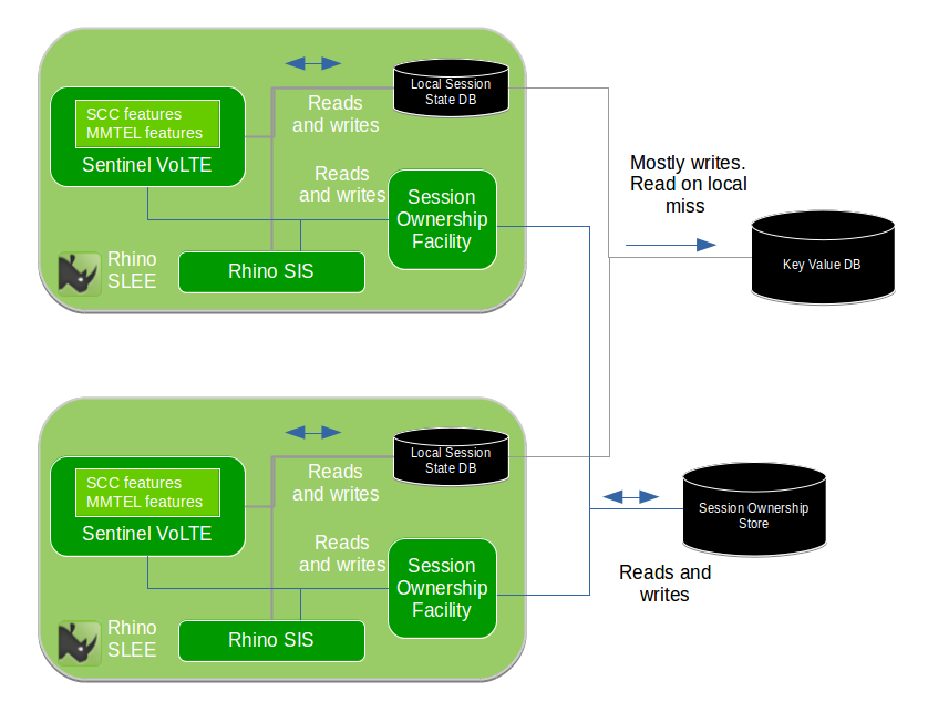
This diagram shows a cluster of two Rhino nodes. The cluster is not limited to two nodes, many nodes run in an active manner. Each node runs in a single multi-threaded Process.
Applications and their components store Session State into the Local Session State Database. The SIS (a component providing the SIP interface) is configured to write state for established dialogs into the Local Session State Database. The Local Session State Database is configured to write data to a Key/Value Store
For further information related to Session State handling, refer to Storage of Session State.
When Session Replication is enabled, a record of which Rhino SLEE node is processing a particular protocol session (e.g. SIP Dialog) is stored by Session Tracking in the Session Ownership Subsystem.
DNS is used to route requests to a preferred node, with a backup address of another node. This mechanism is horizontally scalable. For further information refer to DNS Redundancy and Record Route to enable fail-over of sticky sessions.
Storage of Session State
Session related information is stored in the Rhino platform’s Local Memory Database (MemDB local). This is resident in the JVM heap. Session related information contains variables such as:
-
SIP dialogs used in a B2BUA
-
dialog related information includes the Route set, CSeq and so-on
-
-
Feature state machine variables
-
Control variables for co-ordinating and controlling execution of sessions, and so-on
The Local Memory Database is the master for the data, and is configured to write data externally to a "key-value store" post transaction commit. In non-failure cases, the key-value store is only written to. Reads are served from the Local Memory Database.
In failure cases, a read-miss in the Local Memory Database causes a read to occur in the key-value store. Once the key and it’s value have been read they are then mastered in the Local Memory Database of the reading JVM process.
The "key-value store" is an external database. It is plugged into the data-storage layer of Rhino’s Memory Database (MemDB).
Rhino 2.6.1 includes out-of-the-box support for the Cassandra Database as the "key-value" store. For further information see Key/Value Stores.
In order to avoid inconsistency of the data, where multiple JVMs are accessing local data and not reading the "key-value store" a mechanism called Session Ownership is used.
The Local Memory Database delays local writes before pushing the modified data to the external key-value store. This is because Sessions typically undergo short periods of multiple signalling transactions, followed by relatively long idle periods.
Sequencing of a fail-over
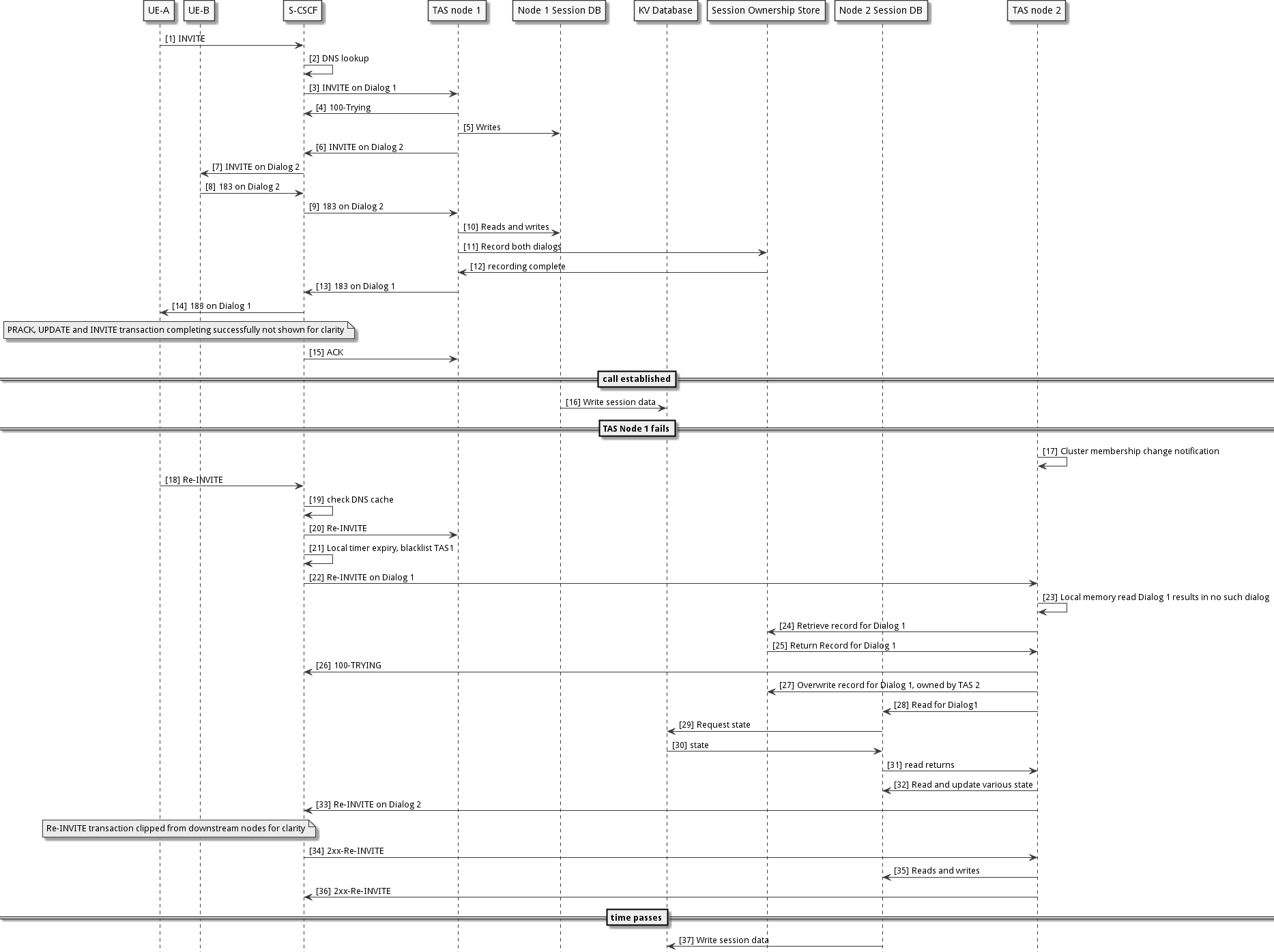
The following sequence demonstrates a call being established, a failure occurring, the call being failed over, the failed node restarting, and the call being anchored on the failed over to TAS node.
-
A call is made resulting in an Initial INVITE request being received at the S-CSCF
-
The S-CSCF performs a DNS SRV lookup as part of iFC, and the result has TAS node 1 as primary and TAS node 2 as a backup (Non-sharded DNS configuration)
-
The S-CSCF sends the Initial Request towards TAS node 1
-
A a 100-TRYING response is received, ensuring TAS node 1 is not blacklisted
-
TAS node 1 executes application logic, that creates various Memory Database entries
-
TAS node 1 acts as a Routing Back-to-Back User Agent (B2BUA) and sends the request downstream (back via the S-CSCF). The request is now on a second dialog. The TAS records route a DNS address, and adds it’s own IP to Via
-
The S-CSCF sends the INVITE downstream, eventually it arrives at the B party UE
-
A dialog creating response is sent following Via
-
the dialog creating response is sent towards TAS node 1 following Via
-
TAS node 1 executes application logic, resulting in reads and writes in the Memory Database
-
TAS node 1 writes records related to each SIP dialog into the Session Ownership store
-
the writes towards the Session Ownership store complete
-
the TAS forwards the dialog creating response upstream on Dialog 1
-
the S-CSCF forwards the response upstream, eventually it reaches the A party UE
-
Time passes and the B party call is answered - note that several round trips are not shown related to QoS negotiation, Ringing, 2xx-INVITE, ACK etc
-
-
TAS node 1 observes the call is answered, and marks the session as eligible for replication
-
the Memory Database for TAS node 1 writes out all necessary data into the key-value Database - this happens asynchronously with respect to protocol signalling
-
Time passes and TAS node 1 fails resulting in Cluster Membership Voting
-
TAS node 2 processes a notification indicating that TAS node 1 is not part of the cluster
-
-
a mid-dialog request is sent from a UE and is routed to the S-CSCF (assuming that the S-CSCF recorded route)
-
the S-CSCF looks at the record-route value for the TAS and checks its DNS resolver cache possibly resulting in a cache hit, or a DNS lookup
-
the S-CSCF proxies the request towards TAS node 1
-
this request times out without a 100-TRYING response received, and black lists TAS node 1 according to RFC XXXX
-
the S-CSCF then proxies the request to TAS node 2
-
TAS node 2 receives the request and checks its local memory (a layer underneath the Local Memory Database) and observes that it does not have any local state for the SIP dialog
-
TAS node 2 reads the Session Ownership Subsystem and observes a record stating that TAS node 1 owns the Dialog
-
TAs node 2 recognises that TAS node 1 is not part of the cluster and decides that it will take over the Dialog
-
this results in it sending a 100-Trying to the S-CSCF
-
TAS node 2 overwrites the row for the dialog indicating that node 2 owns the dialog
-
TAS node 2 then processes the request locally invoking Application logic resulting in reads of the local Memory Database
-
these reads result in a read-miss forcing the local Memory Database to load from the Key Value Database - this blocks the calling logic
-
the Key Value Database responds with the requested entries
-
the blocked read returns control to the calling logic
-
TAS node 2 continues to execute Application logic resulting in reads and writes
-
The request is sent downstream on Dialog 2, the Via includes TAS node 2
-
state modifications are written out to the Key Value database asynchronously to signalling - typically after a delay
The platform includes a capability to enable Session Replication once a session has hit a particular point. In this example replication is enabled post call establishment.
It is typical for a Session to undergo periods of signaling, followed by idle periods, followed by periods of signalling and so on until the Session is ended. The TAS’s local Memory Database delays writes to the Key Value store to avoid immediately overwriting the data in the case that the Session is in the midst of a period of signalling.
Storage of Configuration
Each Rhino cluster stores it’s configuration in Profiles that are backed by a disk based SQL database, PostgreSQL. Each site runs one or more clusters. A cluster does not span sites.
No subscriber data is stored in the platform.
Limitations
The following are documented limitations with Session Replication:
-
Every Rhino/Savanna cluster that connects to a shared Cassandra cluster must have a unique Rhino Cluster ID. There is no checking or validation that the Rhino/Savanna cluster IDs are unique. Therefore either:
-
assign every Rhino cluster a unique cluster ID, or
-
provide each Rhino cluster with its own Cassandra cluster
-
-
Replicated Session data may only be used within a single cluster. This means that a session can fail-over from one cluster member to another, but not across clusters.
-
Replicated Session data is only used within a single Data centre. This means that session fail-over between sites is not supported.
-
Replicating Session data costs CPU cycles and memory, in both Rhino and the Cassandra Database. If a production installation is upgraded and wishes to make use of this capability, then capacity planning/hardware sizing should factored into the upgrade.
