The Access Transfer Update - Session Transfer Identifier (ATU-STI) is a SIP URI assigned to a device during registration, if 3GPP Rel10 (or later) enhanced Single Radio VCC (eSRVCC) is to be applied to that device’s sessions. In releases prior to Sentinel VoLTE 2.6.0 each TAS cluster member was required to have its own ATU-STI. As of release 2.6.0, TAS cluster members may share an ATU-STI, and indeed multiple TAS clusters may also share an ATU-STI.
The ATU-STI is used by the ATCF in order to route an INVITE due to ATU-STI to the SCC-AS as part of PS to CS SRVCC Access Transfer with ATCF enhancements. In the rest of this page, an INVITE due to ATU-STI, or an INVITE due to STN-SR that arrives at the SCC-AS is referred to as a "Handover INVITE".
Every TAS cluster member must be assigned a unique SCC-AS-URI that is routable between the TAS cluster. If multiple TAS clusters share an ATU-STI, then all TAS cluster members must be assigned a globally unique SCC-AS-URI, that must be routable from any node in any cluster, to any other node.
The ATU-STI must be routable between the ATCF (in the visited and home networks) and the SCC-AS (in the home network).
The capability of having a Shared ATU-STI is possible through the SCC-AS using the Session Tracking infrastructure.
Co-ordinating Access Transfer
A device may participate in several sessions at once. For example, it may have an ACTIVE session, and several HELD sessions; or it may have an ACTIVE session and an ALERTING session; and so-on. The SCC-AS signalling anchor instances for each of this device’s sessions may reside on different TAS cluster members, and possibly different TAS clusters. When multiple TAS nodes (regardless of which cluster) share an ATU-STI, a Handover INVITE may arrive at any of the nodes. Yet different nodes may be serving that device’s sessions. Therefore there is a need to co-ordinate Access Transfer between the nodes sharing the ATU-STI.
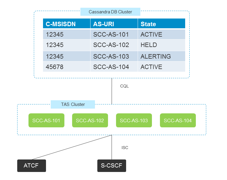
The following diagram shows a four node TAS cluster, where all nodes share a single ATU-STI. There are four sessions in progress. Three sessions share the same Correlation-MSISDN (C-MSISDN) (12345) and so are for the same device. Each session’s signalling anchor is located on different TAS cluster members. The Session Tracking Database (Cassandra) is storing the location and other meta-data (e.g. the SCC-AS-URI, and state fields) related to each of these sessions.

The ATCF addresses the SCC-AS nodes via the ATU-STI. A common DNS configuration for the ATU-STI is to allow all cluster members to be resolved through the ATU-STI. So a single Handover INVITE with a Request-URI set to the ATU-STI will route to one of the four cluster members. A second Handover INVITE with the Request-URI set to the ATU-STI may route to the same, or another cluster member.
Handover INVITEs from the ATCF include the C-MSISDN in the P-Asserted-Identity header. The C-MSISDN is used by the SCC-AS in order to determine the Transferable Set. The Transferable Set includes any session to transfer, as well as any session that will not be transferred and is considered superfluous.
A simple co-ordination example
Assume that the system state is as described in the diagram above.
A Handover INVITE is sent from the ATCF with the Request URI set to the ATU-STI and a C-MSISDN equal to 45678. It is routed to the TAS cluster node SCC-AS-102. This node consults the Session Tracking Database, and observes that C-MSISDN 45678 has a single ACTIVE session, and that session resides on node SCC-AS-104. Therefore it proxies the INVITE request to the AS-URI SCC-AS-104. The TAS cluster node SCC-AS-104 then receives the proxied Handover INVITE and is able to perform SCC-AS procedures for transferring a single active session. In this case, the co-ordination is simply the proxying of an INVITE request.
A more complex co-ordination example
Assume that the system state is as described in the diagram above.
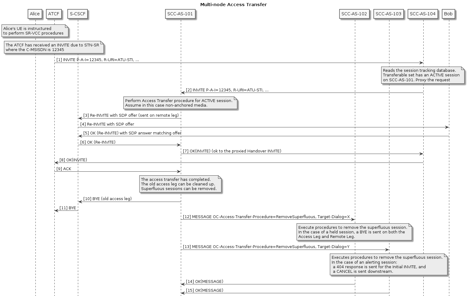
A Handover INVITE is sent from the ATCF with a Request URI set to the ATU-STI and a C-MSISDN equal to 12345. This Handover INVITE is routed to the TAS cluster node SCC-AS-104. The SCC-AS reads the Session Tracking Database and observes that C-MSISDN 12345 has three sessions. An ACTIVE session on node SCC-AS-101, a HELD session on node SCC-AS-102, and an ALERTING session on node SCC-AS-103. Now, the SCC-AS determines that the Transferable Set has a single ACTIVE session, and two superfluous sessions. Therefore the Handover INVITE is proxied to node SCC-AS-101.
Once the node SCC-AS-101 has performed the appropriate procedures to transfer the ACTIVE session, it then signals nodes SCC-AS-102 and SCC-AS-103 instructing them to clean up a superfluous session. It uses a SIP MESSAGE request, containing an OC-Access-Transfer-Procedure Header with an instruction to remove a superfluous session, and a Target-Dialog header indicating which session is superfluous.
The following call flow diagram illustrates this example.

