This document provides instructions for using the Visual Interaction Architect (VIA), a Computer Aided Software Engineering (CASE) tool you can use to build and deploy SIS components (triggers, compositions, and macros).
Audience
This document is for system administrators as well as service developers who intend to use the VIA GUI for creating, deploying, managing, and maintaining the SIS on a Rhino SLEE.
This document assumes a knowledge of the concepts explained in SIS Overview and Concepts.
Scope
This document covers procedures for installing and using the Visual Interaction Architect (VIA) GUI.
This document does NOT focus on:
-
SIS concepts and terminology — see SIS Overview and Concepts
-
installing and starting the SLEE — see the Rhino Production Getting Started Guide
-
tools for Rhino maintenance — see Tools for Managing Rhino
-
troubleshooting — see the Rhino Troubleshooting Guide
About the VIA
VIA offers a visual design environment, with a graphic interface you can use for building SIS components (triggers, compositions, interceptors, and macros) and for deploying them in a SIS.
As explained in SIS Overview and Concepts, the SIS-internal representation of these components are XML descriptor files. With VIA, instead of producing or maintaining this XML manually, you can create the SIS components visually as diagrams (such as trigger diagrams and interaction diagrams). VIA takes over the task of generating the XML descriptors so you can focus on the task of defining service interaction behaviour, rather than writing XML.
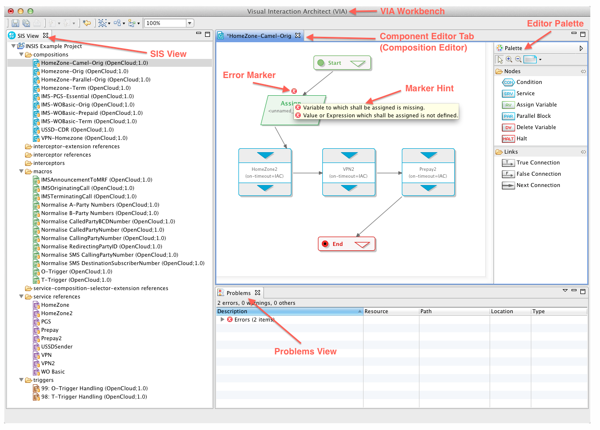
You can also use VIA to deploy and undeploy the SIS components you produce with it into a running SIS. You can use VIA for other management operations as well, such as activating and deactivating triggers. The following screenshot shows key components of the VIA GUI.
| |
For more information on SIS generally, see the SIS Overview and Concepts document. |
Installing VIA
To install VIA:
-
Copy the appropriate release package for your OS and processor to a directory of your choice.
-
Unpack the release package, and run its executable.
Choose Release Package
VIA supports the following platforms.
| OS | Version | Architecture |
|---|---|---|
|
Windows |
Windows XP, Windows Vista, Windows 7 |
x86, 32-bit, 64-bit |
|
Ubuntu |
11.04 or later |
x86, 32-bit, 64-bit |
|
OSX |
10.4 (Tiger) or later |
x86, 32-bit, 64-bit |
| |
Note, for Linux installations please ensure your OS and hardware use the same architecture (for example, a 32-bit OS with a 32-bit processor). |
Package Installation
Installing VIA for Windows
After making sure that you have a working and accessible JVM installed, and downloading the appropriate release package for your system.
1 |
Copy the release package (a `.zip `archive file) to a directory of your choice on your local file system. 
|
|---|---|
2 |
|
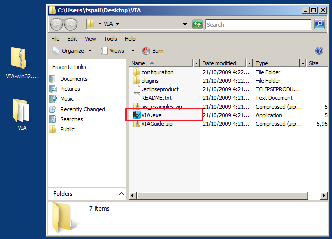
3 |
Run the |
Installing VIA for Linux
After making sure that you have a working and accessible JVM installed, and downloading the appropriate release package for your system:
1 |
Copy the release package (a 
|
|---|---|
2 |
Use the Archive Manager or You should now see a "VIA" subfolder in your directory. 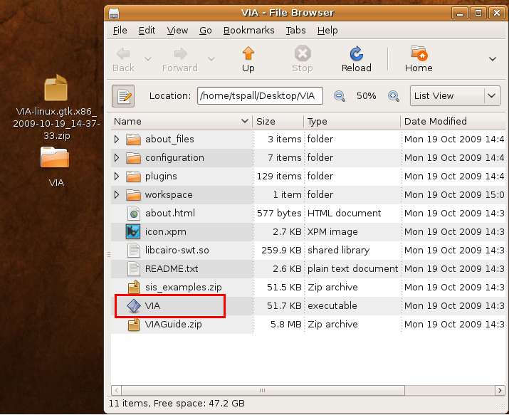
|
3 |
Run the |
Installing VIA for Mac OSX
After making sure that you have a working and accessible JVM installed, and downloading the appropriate release package for your system:
1 |
Copy the release package (a 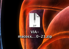
|
|---|---|
2 |
Double click on the 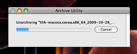
You should now see a 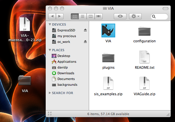
|
3 |
Run the |
4 |
To make things really simple, drag VIA to your taskbar so you can run it any time! 
|
Running for the First Time
This section gives some information and guidance for users who start the VIA for the first time after installation.
In particular, it explains:
Welcome Screen
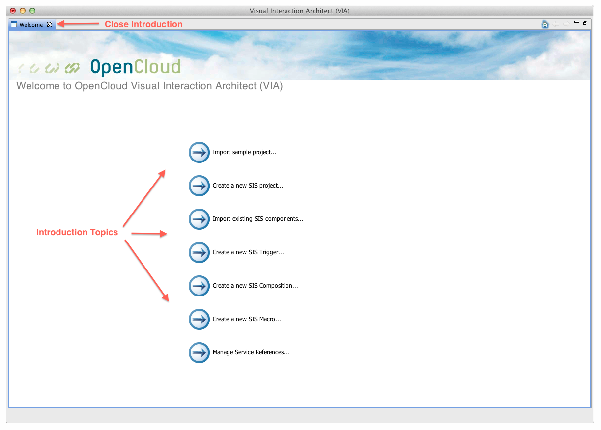
When you start VIA for the first time (after installation), the Welcome screen displays.
It includes a series of links to "Introductory topics", describing popular tasks.
| To… | Do this: |
|---|---|
|
return to the main Welcome screen page from each of the task descriptions |
click the Home icon |
|
close the Welcome screen, and get to the VIA main workbench area |
click the ✖ in the Welcome tab |
|
get to back to the Welcome screen at any time, from the main workbench area |
select Help ▶ Welcome from the Program menu |

Workbench Structure
The VIA main program window is called the workbench.
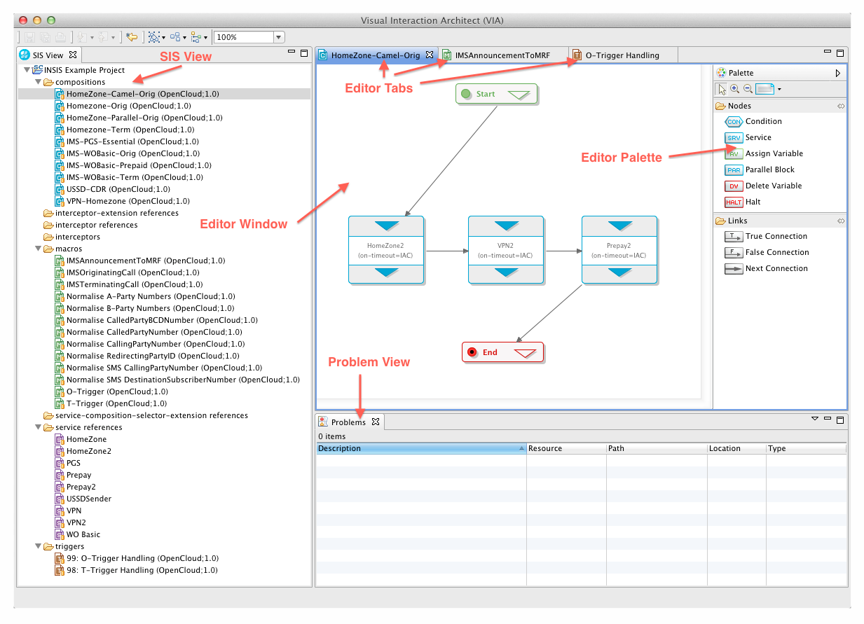
As shown in the illustration, the workbench includes:
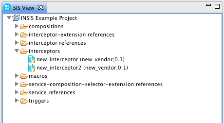
 SIS View — projects open in the VIA, and their SIS components.
-
Double-clicking a SIS component (trigger, macro, interceptor, or composition) opens its diagram in the Editor window.
-
Double-clicking a service reference, extension reference, or interceptor reference opens its properties in a Dialog window.
-
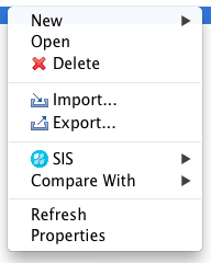
Right-clicking any node in the tree structure opens a context (popup) menu with operations you can perform on that SIS component or part of the project structure.
 Problems view — all error and warning markers in open projects.
 Editor window — SIS component diagrams (tabbed for multiple components).
-
 Editor Palette (part of the Editor window) — visual component nodes, which you can drop onto the diagram canvas (varies depending on the type of diagram editor in the Editor window, for example a composition diagram has different palette entries than a trigger diagram).
Project Concept
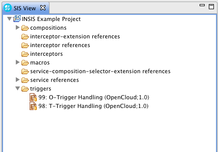
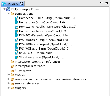
Components in VIA must be organized into projects. The SIS View in the VIA workbench displays projects as top-level entries in a tree structure, with project components (triggers, macros, compositions, interceptors, and references) as their children.
| |
To create a new project, see Create a new project. |
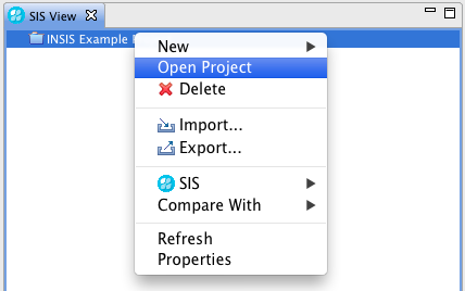
Opening and closing projects
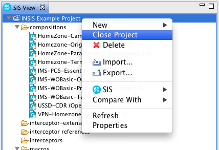
A project can be either open or closed.
| |
To open or close a project, right-click it in the SIS View, and select Open Project or Close Project from the popup menu. |
| |
Closed projects in SIS View don’t display their SIS components or any associated error or warning markers. |
Project properties
Each project has a set of associated properties
| |
To display project properties, right-click the project node in the SIS View, and select Properties from the popup menu. (See Configure project settings for details.) |
| |
SIS connection properties are part a project’s property configuration. (See Managing live SIS deployments with VIA for details.) |
Creating SIS Components with VIA
This section explains how to use VIA to: create the various SIS components, organize them into project structures, validate (and fix) them, and retrieve the XML VIA generates for them.
It includes the following topics:
| |
Are you a first time user? Try reading Running for the First Time. |
Import Example Project
The VIA distribution package comes with an example project that you can can import into the workbench.
Use the import wizard:
1 |
In the SIS View, right-click in the background and select Import… from the popup menu. 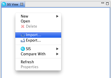
The Import Wizard opens. |
|---|---|
2 |
Select General ▶ Existing Projects into Workspace. 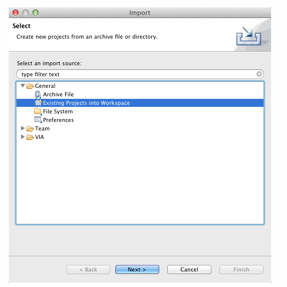
|
3 |
Activate the Select archive file radio button, click the Browse button, and navigate to the sis_examples.zip file (in the 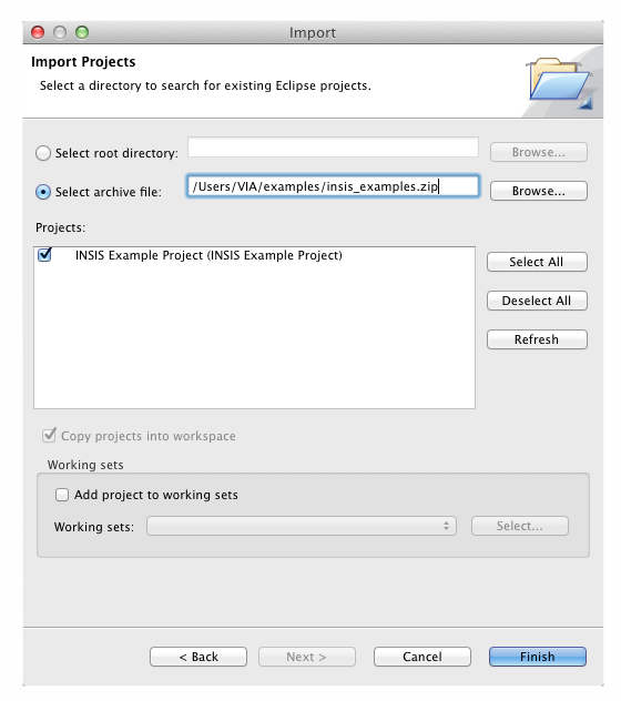
|
4 |
Click OK. VIA imports the project into the workbench, and the SIS View shows its various components. 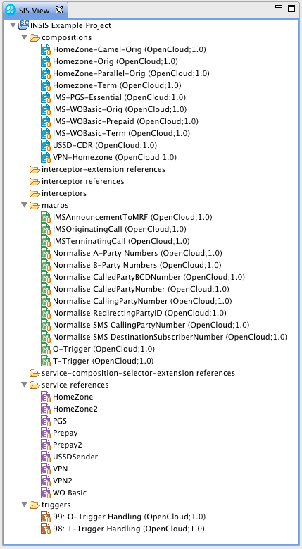
|
Create a New Project
| |
Before you can create SIS components in VIA, you need a project to associate them with. The workbench lists existing projects in the SIS View, as root node elements: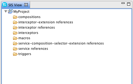 |
To create a new project:
1 |
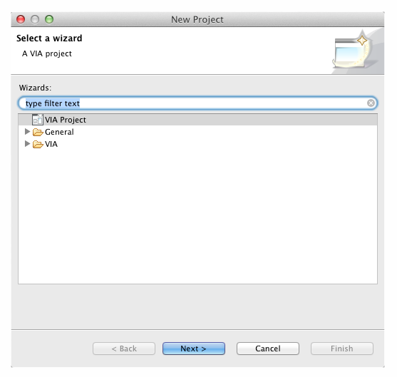
Click select New ▶ Project… from the File menu. 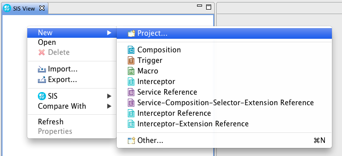
|
||||
|---|---|---|---|---|---|
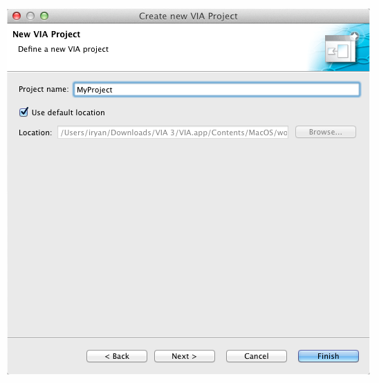
2 |
Choose VIA Project, click Next, and enter a name for your project.
|
||||
3 |
Otherwise, click Next. Options display for you to set up the properties for the management connection to a live SIS. 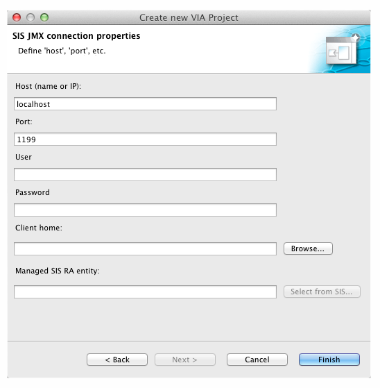
|
Triggers
| |
What are triggers?
Triggers are SIS components that select the proper service compositions for each incoming request. To do this, they make use of three different lookup mechanisms, modeled as selector elements in the VIA’s trigger diagrams. For more about triggers generally, see Triggers in the SIS Overview and Concepts document. |
Creating a New Trigger
To create a new trigger:
1 |
Select New ▶Trigger from the File menu. 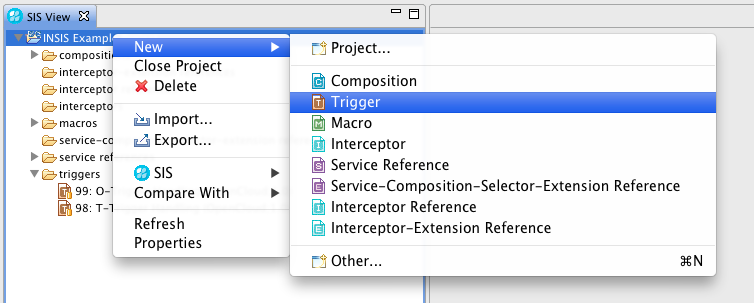
The Trigger Creation Wizard opens. |
||
|---|---|---|---|
2 |
Select the project you want the new trigger to belong to, and click Next. 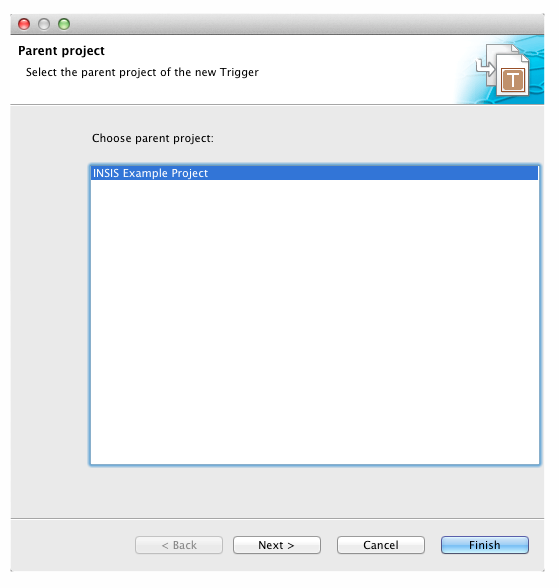
The wizard prompts you to specify trigger properties. |
||
3 |
Enter the trigger’s:
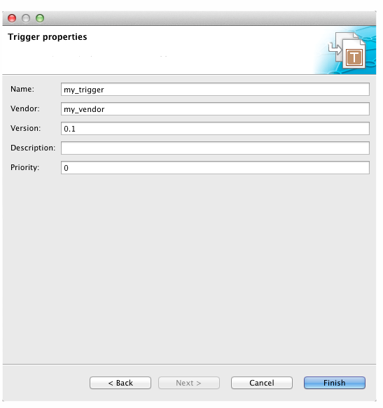
|
Trigger Diagram Elements
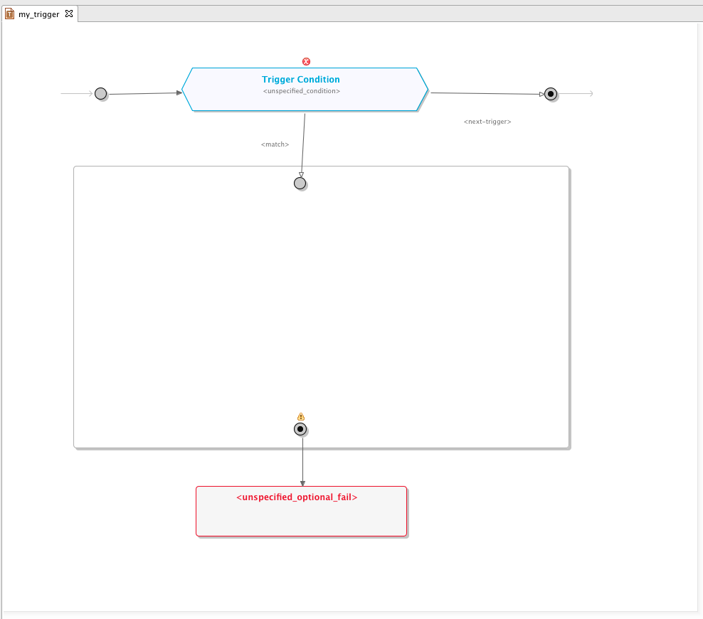
To open a trigger diagram, double-click the trigger’s icon in the SIS View trigger list. Below is an example of a trigger diagram, plus details on the trigger condition element, selector components compartment, and trigger terminate element.
Trigger diagram
Below is an example of a freshly created trigger.
| |
To change the properties of any diagram element, double-click it. A dialog pops up for changing element properties. |
Trigger condition element
A trigger condition defines when the SIS evaluates a trigger’s selector components (to select a service composition). On an incoming request from the network:
-
The SIS starts looking through the list of triggers sequentially, starting with the one with the highest priority.
-
If a trigger’s trigger condition evaluates to true, the SIS starts running through the trigger’s selector components.
-
If the trigger condition evaluates to false, it proceeds to the next trigger in the priority list.

| |
To configure the trigger condition, double-click the grey polygon with the condition’s textual description (or <unspecified_condition> if none is set yet).The Condition Editor opens in a new editor tab. |
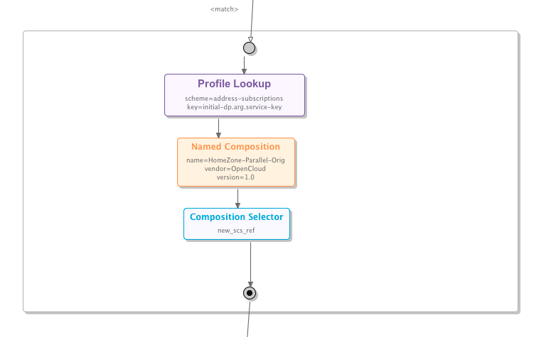
Selector components compartment
Selectors are the trigger components responsible for finding and returning the appropriate service composition to run. There are three types: profile lookups, named composition, and composition selector extension (for details, see Composition Selection in the SIS Overview and Concepts document).
| |
To configure selectors
During runtime, the SIS uses the result of the first selector in the chain that finds and returns a valid composition. |
Trigger terminate element
If a trigger’s trigger condition evaluates to true, but none of its selectors finds an appropriate service composition to run, the SIS proceeds to the trigger terminate configuration and takes a corresponding action.
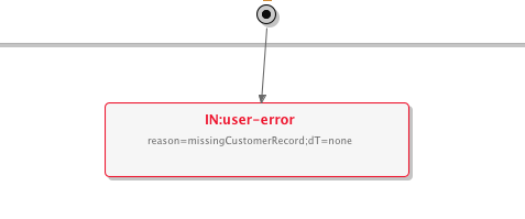
| |
A SIS trigger is not required to have a terminate configuration, so the trigger terminate diagram element can stay unconfigured. |
Compositions
| |
What are compositions?
Compositions are SIS components that specify the sequence in which to invoke a set of services. They can include quite complex branching logic, and even parallel invocation of services. (For details, see Compositions in the SIS Overview and Concepts guide.) |
Creating a New Composition
To create a new composition:
1 |
Select New ▶ Composition from the File menu. 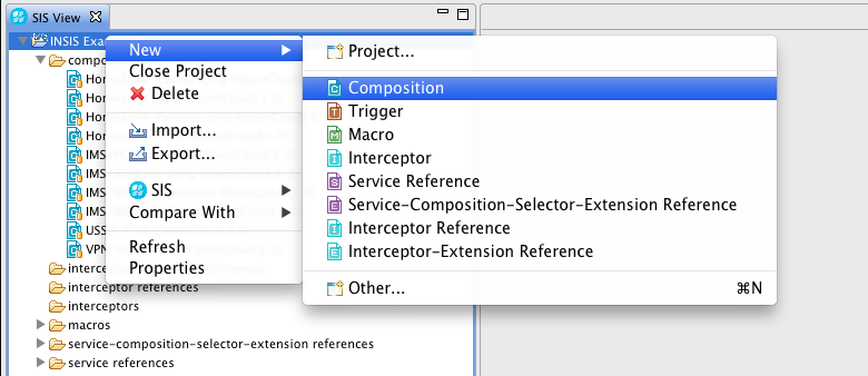
The Composition Creation Wizard opens. |
||
|---|---|---|---|
2 |
Select the project you want the new composition to belong to, and click on Next. 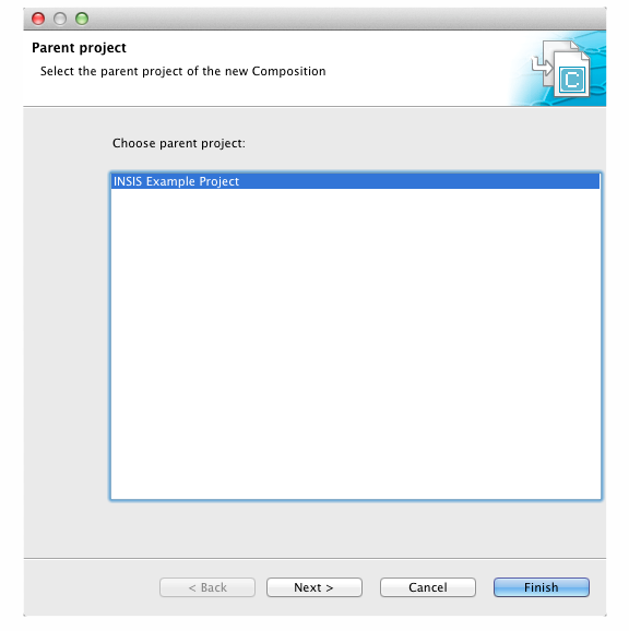
The wizard prompts you to specify trigger properties. |
||
3 |
Enter the composition’s:
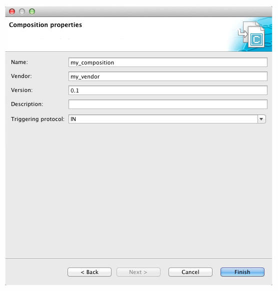
|
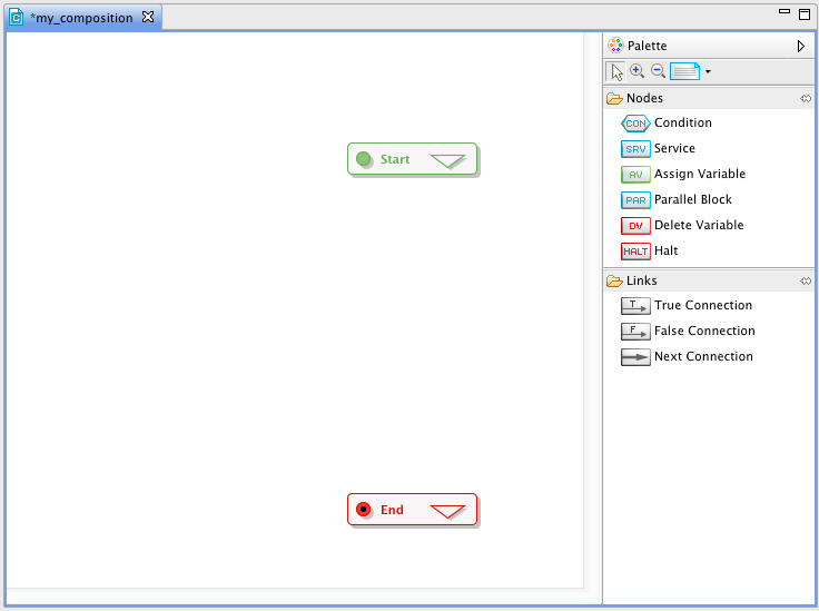
Composition Diagram Elements
To open a composition diagram, double-click on the composition’s icon in the SIS View composition list. Below is an example of a freshly created composition diagram, plus details on the composition start and end, service, variable manipulators, condition (branching), halt,and parallel block elements.
The control flow:
-
starts at the composition start. From here you connect to other elements (Condition, Service, Assign, and so on) using the connect link from the palette. The connect link defines a next statement relation. You use it to specify the sequence of script statements in the composition.
-
ends at the composition end element.
Composition diagram
Below is an example of a freshly created composition. It includes a start node (top-left) and an end node (bottom-right).
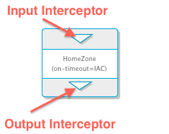
Composition start and end
The composition start and composition end represent the entry and exit points of the composition from the perspective of an incoming initial message from the network. Composition start and end points may also include a signalling interceptor (the triangle on the start/end element).
|
|
|
Composition start |
Composition end |
|---|


The composition input interceptor lets you manipulate the composition environment (setting variables, invoking extensions, and so on) before executing any of the composition’s service invocations or combining logic. The composition output interceptor can be used to perform manipulations after the composition’s service execution logic.
| |
To configure either of these interceptors, double-click the white arrow in its symbol. The interceptors content opens in a new Editor tab. |
Service element
The Service element specifies how to invoke a service (either local or external). The element does not name the service directly — it uses one of the service reference names (which in turn refers to either a local SLEE service or an external platform). As well as service reference name, you can configure other parameters (such as the timeout period and behaviour on timeout).
| |
To change the service invocation parameters, double-click the area at the centre of the Service icon, containing the service reference name. A dialog with service parameters displays. |
| |
Each service:
|
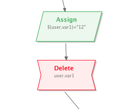
Variable manipulator elements (assign, delete)
Through the assign element, a variable can be set to:
-
a specific value,
-
the value of any other existing variable
-
a complex variable type (such as a
CalledPartyNumber) -
the result of a string-manipulation function (such as a substring or string-length).
Through the the delete element, an existing variable can be "unset".

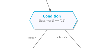
Condition (branching) element
The Condition element represents a conditional selection within the composition’s flow chart logic. It has two outgoing connections:
-
<true>— followed if the condition evaluates totrue(created using the if-true link from the palette) -
<false>— followed if the condition evaluates tofalse(created using the if-false link from the palette)
| |
A Condition statement must always have both, a <true> and <false> connection. |
| |
To edit a Condition, double-click anywhere on the icon (which contains the condition’s textual representation at its centre).The Condition Editor opens in a new Editor tab. |
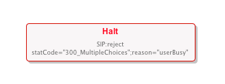
Halt element
Halt elements allow you to stop the composition at any point during the script run. After encountering a halt, the SIS will evaluate no more composition instructions and proceed to the composition end.
For SIP, a halt element can be configured with a failure response, indicating what shall be sent to the network.
| |
Halt elements cannot have an outgoing connection to another diagram element as they represent terminals of the invocation chain. |
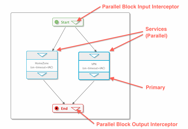
Parallel block element
A parallel block allows you to define a set of services that should run in parallel, and meet at a synchronization point.
| |
Each parallel block has input and output signalling interceptor elements, to modification of signalling before any service runs, or after all included parallel services have run. |
| |
To add a new parallel service to a block, use the Service tool from the Palette, to drop a new service into the Parallel Block compartment. (Configure parameters and interceptors for these services the same way as "normal" services). |
| |
Each parallel service has to connect directly to the parallel block’s output interceptor, and cannot connect to another parallel service. In other words, you cannot run two parallel services in a row. (May be supported in future version of SIS.) |
| |
Each parallel block has individual timeout and timeout-handling parameters (similar to a service generally). To change them, double-click the parallel block background. A popup dialog, similar to the one for configuring services, displays. |
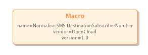
Macros
| |
What are macros?
Macros are reusable functional blocks, which can be referenced from other macros, or used in conditional expressions in compositions or triggers. They have a double-sided nature:
In VIA, macros are modeled as condition tree structures, with individual nodes being either Boolean operators (such as |
Creating a New Macro
To create a new macro:
1 |
Select New ▶ Macro from the File menu. 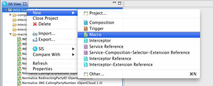
The Macro Creation Wizard opens. |
||
|---|---|---|---|
2 |
Select the project you want the new macro to belong to, and click Next. 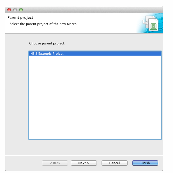
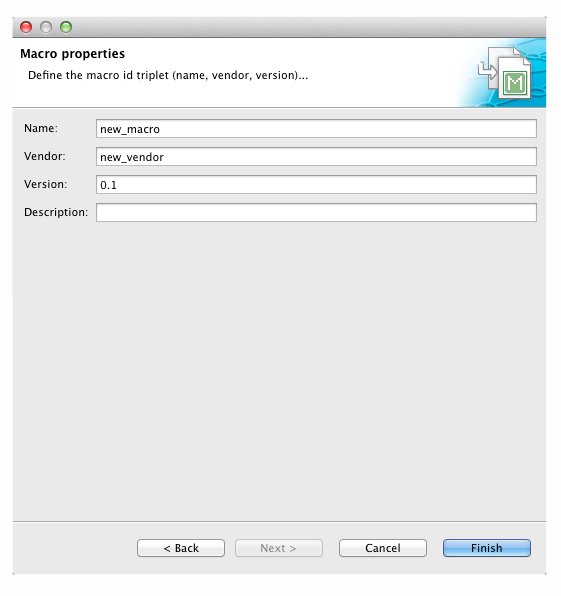
The wizard prompts you to specify macro properties. |
||
3 |
Enter the macro’s:
|
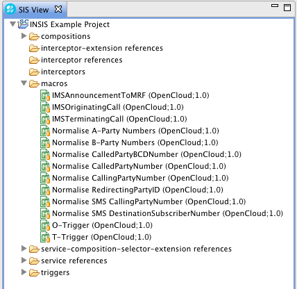
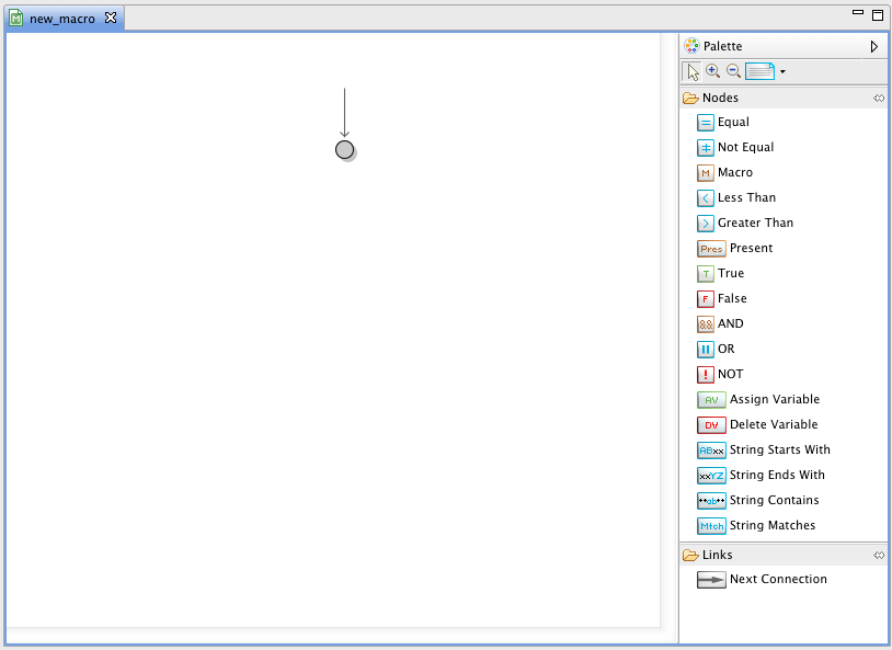
Macro Diagram Elements
To open a macro diagram, double-click the macro’s icon in the SIS View macro list. Below is an example of a macro diagram, plus details on comparator, string, present, variable, literal, group operators, and macro invocation elements.
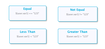
Comparator elements (equal, not-equal, greater-than, less-than)
Comparator elements work the same as well-known operators named similarly. Each operand/parameter can be:
-
a specific value
-
the value of any other existing variable
-
a complex variable type (such as a
CalledPartyNumber) -
the result of a string-manipulation function (such as a substring or string-length).
| |
To configure a comparator element:
A dialog opens to configure the two operands for the comparason. |
Special string elements (starts-with, ends-with, contains, matches)
These operators, which return true or false (like comparator elements), check whether text strings start with, end with, or contain a sub-string; or match a regular expression.
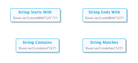
| |
To configure a string element, double-click it. A dialog opens to set the values and variables for the operation. |
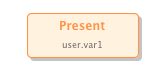
Present element
The present element checks if a variable is set — if (at the time of the check) it’s in the list of global variables that the SIS keeps.
Variable manipulator elements (assign, delete)
Through the assign element, a variable can be set to:
-
a specific value,
-
the value of any other existing variable
-
a complex variable type (such as a
CalledPartyNumber) -
the result of a string-manipulation function (such as a substring or string-length).
Through the the delete element, an existing variable can be "unset".

| |
An assign or delete element implicitly always evaluates to true. |

Group operators (and, or, not)
Group operator elements represent the logical and, or, and not operators. As such, they are the only elements in a condition tree diagram (except the tree root) which have successor elements.

| |
The SIS scripting language uses short-circuit boolean evaluation. In this current release of VIA,, the order of arguments to You can view the generated XML in VIA to check that your expression is indeed correct. To fix any problems, you can simply remove the connections to each parameter in your |
Interceptors
| |
What are interceptors?
An interceptor is a set of script elements that may modify the parameters of the messages it intercepts (or may perform some other action). For more about interceptors generally, see Interceptors in the SIS Overview and Concepts document. |
Creating a New Interceptor
To create a new interceptor:
1 |
Select New ▶ Interceptor from the File menu. 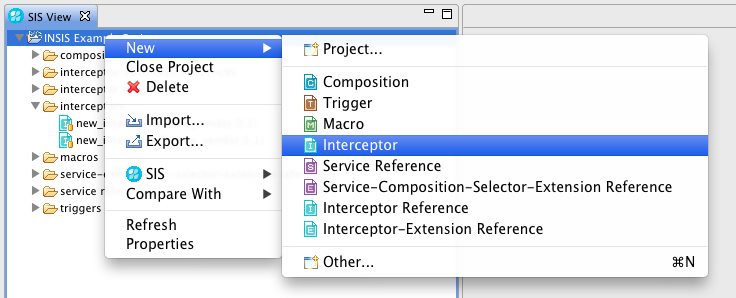
The Interceptor Creation Wizard opens. |
||
|---|---|---|---|
2 |
Select the project you want the new interceptor to belong to, and click Next. 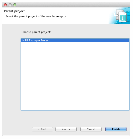
The wizard prompts you to specify interceptor properties. |
||
3 |
Enter the interceptor’s:
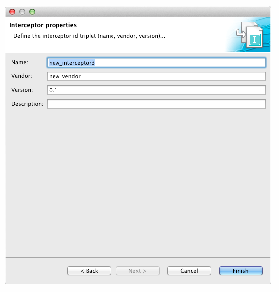
…and click Finish. VIA creates the interceptor. |
Interceptor Diagram Elements
To open a interceptor diagram, double-click on the interceptor’s icon in the SIS View interceptor list.
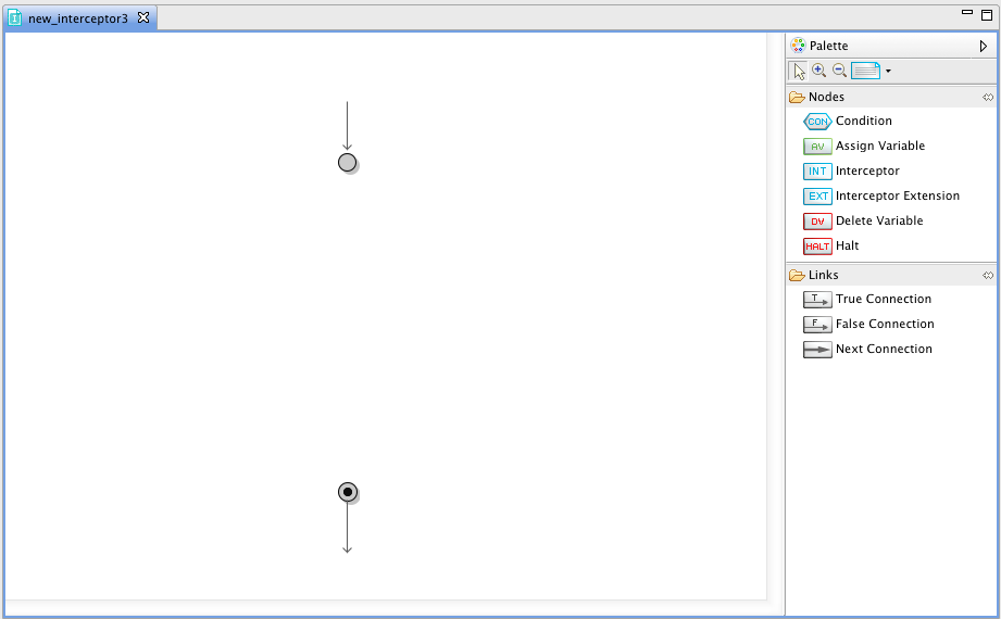
Below is an example of a freshly created interceptor diagram, plus details on the variable manipulators, condition (branching), and halt elements.
The control flow:
-
starts at the interceptor start element. From here you connect to other elements (Condition, Assign, Delete and so on) using the connect link from the palette. The connect link defines a next statement relation. You use it to specify the sequence of script statements in the interceptor.
-
ends at the interceptor end element.
Interceptor diagram
Below is an example of a freshly created interceptor. It includes a start node (top) and an end node (bottom).
Variable manipulator elements (assign, delete)
Through the assign element, a variable can be set to:
-
a specific value
-
the value of any other existing variable
-
a complex variable type (such as a
CalledPartyNumber) -
the result of a string-manipulation function (such as a substring or string-length).
Through the the delete element, an existing variable can be "unset".
Condition (branching) element
The Condition element represents a conditional selection within the composition’s flow chart logic. It has two outgoing connections:
-
<true>— followed if the condition evaluates totrue(created using the if-true link from the palette) -
<false>— followed if the condition evaluates tofalse(created using the if-false link from the palette).

| |
A Condition statement must always have both, a <true> and <false> connection. |
| |
To edit a Condition, double-click anywhere on the icon (which contains the condition’s textual representation at its centre). The Condition Editor opens in a new Editor tab. |
Halt element
Halt elements allow you to stop the interceptor at any point during the script run. After encountering a halt, the SIS will evaluate no more interceptors instructions, and proceed to the interceptor end.
For SIP, a halt element can be configured with a failure response, indicating what shall be sent to the network.

| |
Halt elements cannot have an outgoing connection to another diagram element, as they represent terminals of the invocation chain. |
Service and Extension References
You manage both service references and extension references through the SIS Management API.
| |
Service references and extension references are conceptually similar, but managed separately, with separate namespaces. While a service reference and extension reference can have the same name, this is not recommended — it easily gives rise to confusion! |
Service References
| |
What are service references?
Service References are abstractions for a service that a SIS composition invokes at runtime. The service can be either:
|
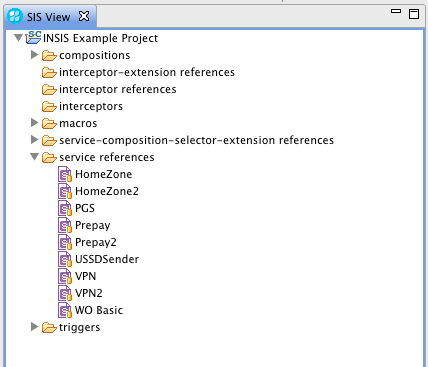
Viewing service references in VIA
Each project shown in the SIS View contains a service references category, which lists all the service references in the project.
| |
Each entry here appears as an entry in the service reference dropdown list for configuring a Service element in a composition diagram. 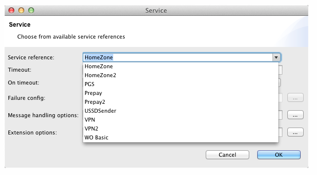
|
See also
Creating a New Service Reference
To create a new service reference in VIA:
1 |
Select New ▶ Service Reference from the File menu. 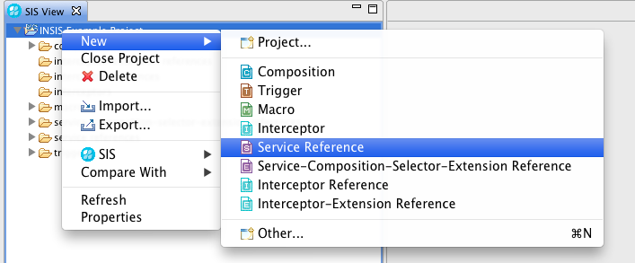
The Service Reference Creation Wizard opens. |
||
|---|---|---|---|
2 |
Select the project you want the new service reference to belong to, and click Next. 
The wizard prompts you to specify service reference properties. |
||
3 |
Enter the service reference’s:
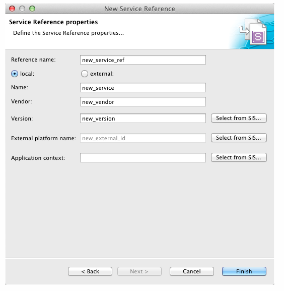
Figure 1. Local Properties
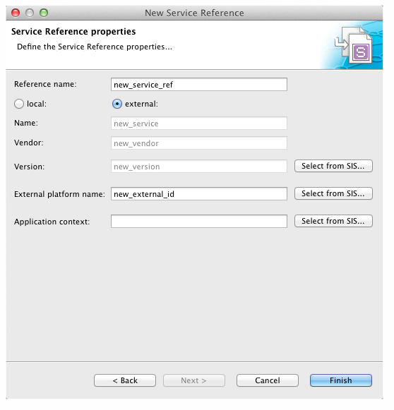
Figure 2. External Properties
|
Extension References
| |
What is an extension reference?
An extension reference is a managed, symbolic name which refers to a SIS extension. A SIS extension, in turn, can be used to change and extend the behaviour of the SIS in cases where the standard elements are not sufficient. See User Extensions in the SIS Overview and Concepts document for details. |
There are two types of extension references, for:
-
Service Composition Selector (SCS) extensions — look up composition scripts as trigger selectors (see Trigger Diagram Elements)
-
Interceptor extensions — used within any of the interceptors (Composition Input/Output, Service Input/Output or Parallel Block Input/Output) to modify a composition’s environment.
Service Composition Selector (SCS) extension references
To create a new SCS extension reference:
1 |
Select New ▶ Service-Composition-Selector-Extension Reference from the File menu. 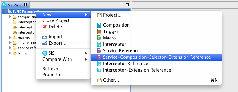
|
|---|---|
2 |
Follow the usual steps through the wizard, until you reach the properties page. All SCS extensions bind to a local SLEE service, so enter the (name, vendor, version) triplet of the extension’s service into the appropriate fields. Then click Finish. 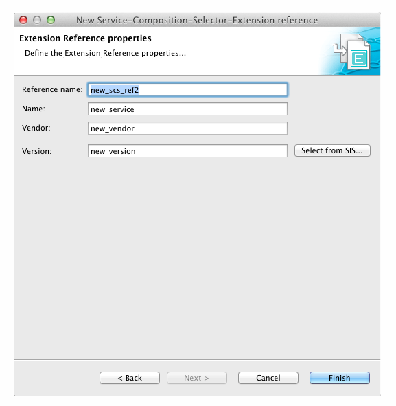
After the new SCS extension reference has been created, its name will appear as an entry in the dropdown list of Service Lookups in Trigger diagrams. |
Interceptor extension references
To create a new interceptor extension reference:
1 |
Select New ▶ Interceptor-Extension Reference from the File menu. 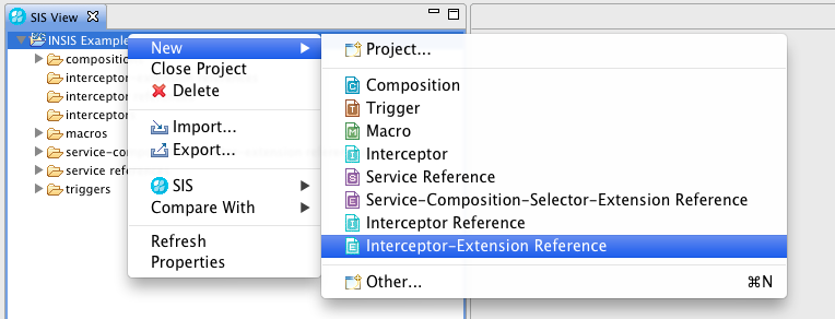
|
|---|---|
2 |
Follow the usual steps through the wizard, until you reach the properties page. All Interceptor extensions bind to a local SLEE service, so enter the (name, vendor, version) triplet of the extension’s service into the appropriate fields. Then click Finish. 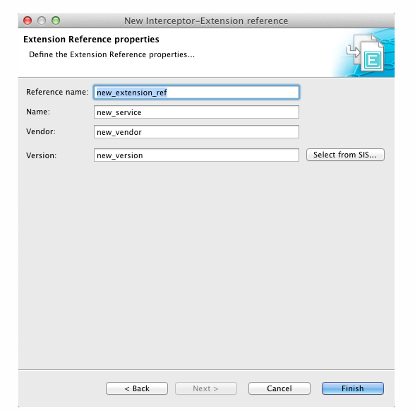
After the new Interceptor extension reference has been created, its name will appear as entry in the dropdown list of Extension elements in interceptor diagrams. 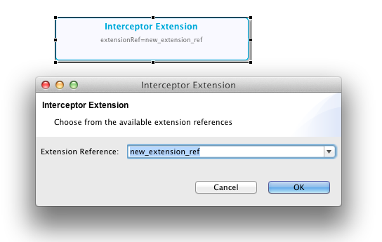
|
Component Validation
Each time you save a change to a diagram, VIA validates the diagram’s elements and their settings. If there are any problems, it will generate appropriate warnings or errors, and suggest "quick fix actions".
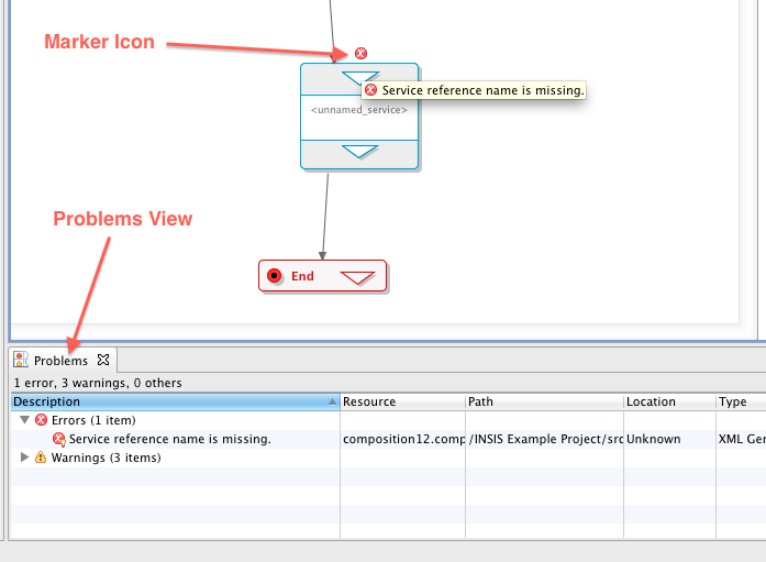
Error markers
Warnings or errors show up as Error Markers in the Problems View below the main editor window, and as little error or warning icons above the diagram element:
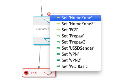
Quick fix actions
For each generated error or warning marker, VIA tries to generate a suggestion to fix the problem. Click the error or warning icon above the diagram element to display a popup menu of suggestions:
Access to Generated XML
You should be able to carry out all SIS-related tasks using the VIA’s diagrams and features (so you wouldn’t normally need access to the underlying XML).
You can, however, look at the XML by using the Project Explorer view:
1 |
The Project Explorer view is hidden in the default perspective, so it is not automatically visible when you start VIA for the first time. To display it, click Show View ▶ Project Explorer from the Window menu. 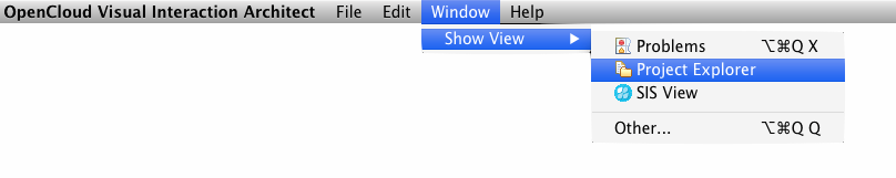
The Project Explorer displays next to the Problems View below the main editor window. |
|---|---|
2 |
In the Project Explorer view, open the node of the project you are working on. All generated XML code is located in the 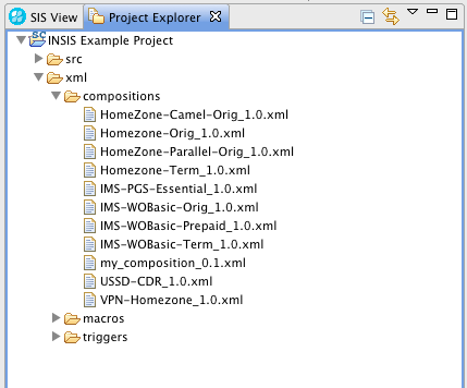
|
3 |
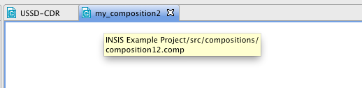
To find the correct XML for a particular diagram component, you will need to find out its filename. To do this:
|
4 |
Use the Project Explorer to open and view the .xml file directly in the VIA’s text editor (or export it into the file system by right-clicking on the file and choosing Export… from the popup menu). |
| |
If you display the generated XML in the VIA’s text editor, open the file as read-only. Manual changes to the generated XML code in the internal (or an external) text editor will NOT be updated into the diagram. In fact, VIA will simply overwrite any such changes without notice, the next time it generates the XML the diagram source. |
Managing Live SIS Deployments with VIA
This section explains how to use the Visual Interaction Architect (VIA) to manage the SIS components in a working project. This includes deploying and undeploying components to and from a SIS, running on the same or a different host that is accessible through the SIS Management API.
| |
VIA can perform management actions directly, using the setup management connection — so there is no need to export components' generated XML code for manual deployment. |
| |
For now, pre-production only
The management functionality in VIA is still widely under development. Although the current features are sufficiently powerful to substantially support development with a pre-production environment, manual management using |
See also:
Configure Project Settings
To connect successfully to an external running SIS using the Management API, properties such as username and password must be set.
VIA keeps these properties per project, as part of the project configuration data. You enter these settings when creating a project. To change them later:
1 |
Click the project root entry in the SIS View, and select Properties from the popup menu. 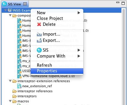
A Property dialog displays. 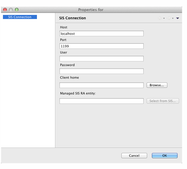
|
|---|---|
2 |
You can change any of the following connection settings:
|
| |
SIS components can "belong" to multiple SIS-RA entities at once (by sharing configuration profiles). In VIA, however, this is not supported. VIA assumes that a certain SIS component only belongs to exactly one SIS-RA entity. This might create problems in cases where in existing deployments, for example, triggers are associated with multiple RA entities — when trying to undeploy such a trigger, which is active on both entities, through VIA, the undeploy operation will fail (as the VIA will only deactivate the trigger on one of the RA entity before trying to do the undeployment). In this case, as a workaround, you need to:
|
Update from a Running SIS
VIA can update a project’s content with the deployments in a running SIS, through a management connection.
The update operation can be run in the SIS View on either:
-
a project node, or
-
one of the sub-category nodes (such as triggers or compositions).
To initiate the update operation right-click the node in the SIS View, and select SIS ▶ Update from the popup menu.
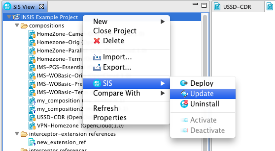
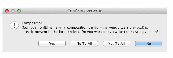
The VIA then tries to set up a management connection to the existing running SIS. If successful, it downloads the components found there into the local project. For each freshly downloaded component, VIA creates a new diagram and includes it in the project. For existing diagrams that represent a component also found in the SIS, VIA asks whether or not to overwrite the existing version.
Activate or Deactivate Triggers
To activate or deactivate a trigger in a VIA project that matches the ID of a trigger deployed in the external SIS right-click the trigger entry in the SIS View, and select SIS ▶ Activate or SIS ▶ Deactivate from the popup menu.
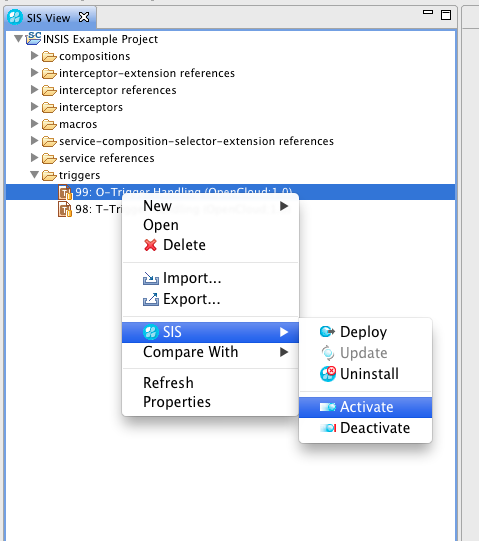
Deploy or Undeploy Components
To deploy or undeploy components in a VIA project right-click the components in the SIS View, and select SIS ▶ Deploy or SIS ▶ Uninstall from the popup menu.
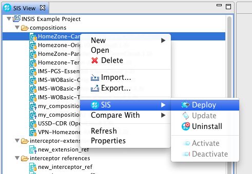
When deploying a set of components, VIA automatically reorders them so that the deployment sequence satisfies any interdependencies between the components. (For example, if Macro-A depends on Macro-B: to select and deploy them as a set, VIA makes sure to first deploy Macro-B (before deploying Macro-A).
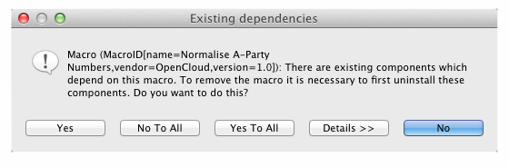
When undeploying components, VIA automatically checks with the externally running SIS whether any deployed components depend upon the components to be undeployed. If so, VIA lists the depending components and asks whether to undeploy them as well.
Fine-Tuning the Configuration
You can change global and project-specific VIA properties and settings through the following configuration files:
| Configuration file | Location | Properties and settings |
|---|---|---|
via.properties |
the |
global VIA configuration properties and settings, including:
|
.sis |
the base folder of each VIA project in the workspace |
project-specific VIA configuration properties and settings, including:
|
You need to restart the VIA to effect any changes to its configuration files.
Example: adding a global variable
To include a new variable to the variable-selection boxes throughout the VIA GUI, you would add its name to the semicolon-separated list of variable names of one or more of the following properties in via.properties:
in_sis_writable_variables=...
in_sis_variables=...
sip_sis_variables=...
sip_sis_writable_variables=...
Example: adding a service reference to a project
Normally, you would manipulate service and extension references through operations in the VIA GUI. Although it’s discouraged, you could instead manually add a service reference to a local service for a project — by adding the reference string, in the following format, to the list of references in the property service-refs in the project’s .scim file:
service-refs=<service-ref-name>;local;<service-name>;<service-vendor>;<service-version>@...