This document explains how to use the OpenCloud Scenario Editor to create scenario definitions, for use with the OpenCloud Scenario Simulator.
Topics
explains how to start the editor, and reviews the components of the main Scenario Editor interface. |
|
describes how to create and edit a scenario, its roles, dialogs, and messages. |
|
explains how to use tools included with the Scenario Editor for reviewing protocol and scenario information. |
|
documents common problems you may find using the Scenario Editor, and how to resolve them. |
Other documentation for the Scenario Simulator, including the changelog and links to downloads, can be found on the Scenario Simulator product page.
Getting Started
Below are basic instructions and command-line options for starting the Scenario Editor.
Basic usage
To start the Scenario Editor, double-click the scenario-editor.bat start script (Windows):
scenario-editor.bat
or by running the following from the command line (Linux/Solaris):
./scenario-editor.sh
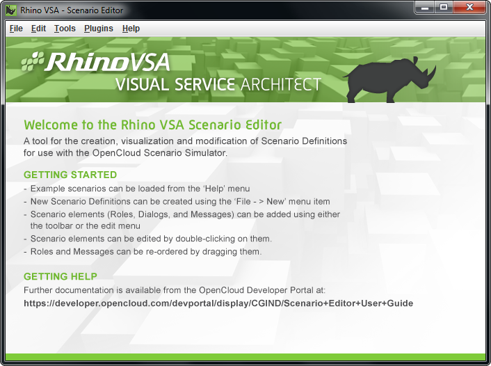
The main Scenario Editor window opens and displays an introductory page.
| |
|
| |
…or open
scenario-editor.jar
You can also open the Scenario Editor by double-clicking java -jar lib/scenario-editor.jar |
Command-line options
From the command line, you can include options with the Scenario Editor, like this:
java -jar scenario-editor.jar [options] [scenarios]
for example
java -jar scenario-editor.jar -m MyScenario1.scen MyScenario2.scen
The Editor opens scenarios specified on the command line when it starts.
Three options are available:
| Option | Abbreviation | What it does | ||||||
|---|---|---|---|---|---|---|---|---|
--help |
-h |
Displays help on command-line options. |
||||||
--dirty |
-d |
Marks scenarios loaded from the command line as 'dirty'.
|
||||||
--migrate |
-m |
Tries to migrate scenarios specified to the latest schema version. For example, with Linux, to migrate all scenarios in a directory to CGIN v1.4: java -jar scenario-editor.jar -m `find scenarios -iname \*.scen`
|
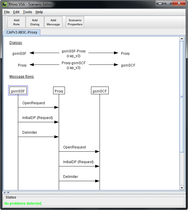
Main Interface
The main Scenario Editor interface consists of the menubar, toolbar, scenario list, dialog list, message flows, and status panel, as follows:
MenubarIncludes these menus:
|
|
||
|
|||
|
|||
|
|||
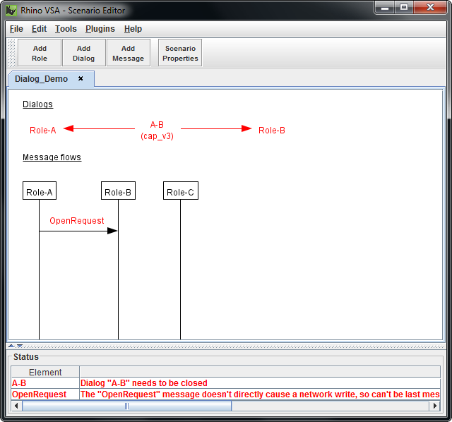
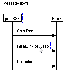
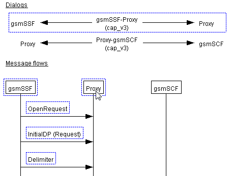
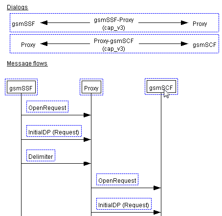
Message flowsThe second part of the Call Flow Editor, for the loaded scenario, shows:
The currently selected messages are highlighted with a blue border. |
|
||
|


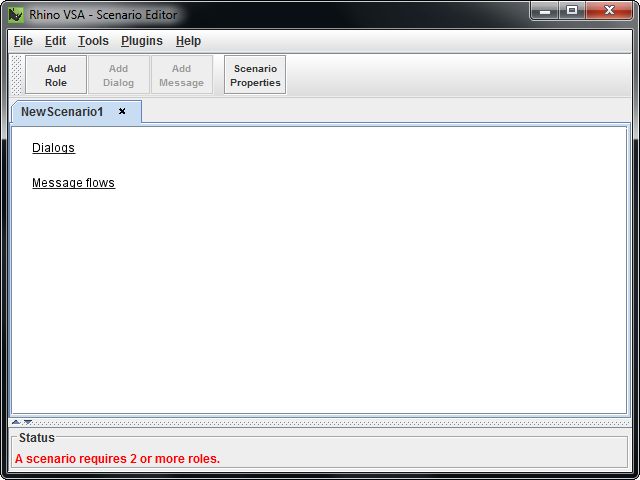
Creating a Scenario
To create a new scenario:
1 |
Select New from the File menu, or press Ctrl+N. A NewScenario<#> tab (numbered sequentially) displays with a new (empty) scenario.
|
||
|---|---|---|---|
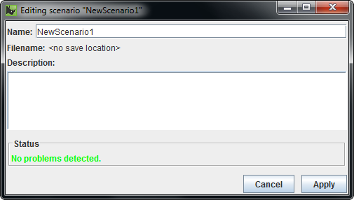
2 |
To name the scenario, select Scenario Properties from the Edit menu, or click Scenario Properties on the toolbar, or double-click the scenario’s name on the tab. The Editing scenario <scenario name> dialog box displays.
|
||
3 |
Type over the name (and optionally add a description) for the scenario, and click Apply. The name displays on the scenario tab. |
Adding and Editing Roles
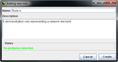
To create a role:
1 |
Select Add Role from the Edit menu, or click Add Role on the toolbar. The Adding New Role… dialog box displays.
|
||
|---|---|---|---|
2 |
Type a name and description for the role, and click Create. The roles display in the Scenario Editor.
|
| |
Editing, re-ordering, and deleting roles
|
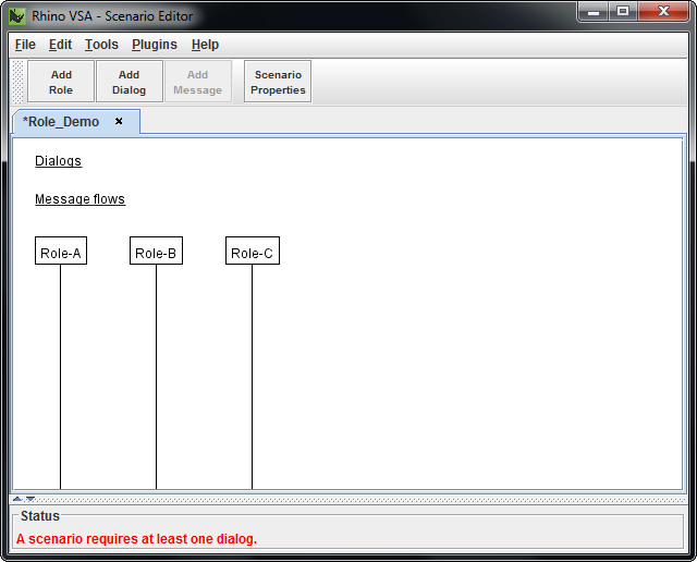
Adding and Editing Dialogs
| |
Dialogs can only be created between existing roles (so before you can create a dialog, you must create at least two roles). |
To create a dialog:
1 |
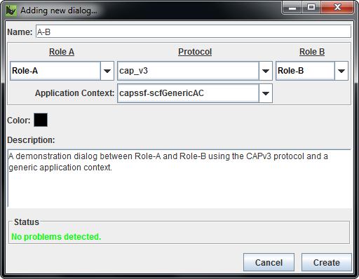
Select Add Dialog from the Edit menu, or click Add Dialog on the toolbar, or drag between roles lines. The Adding a New Dialog… dialog box displays.
|
||
|---|---|---|---|
2 |
Select roles and a protocol from the drop-down lists, type a name and description for the dialog, and click Create. The dialog displays in the dialog list at the top of the Scenario Editor.
|
| |
Editing and deleting dialogs
|
Adding and Editing Messages
| |
Messages can only be created on an existing dialog (so before you can create a message, you must create at least one dialog). |
To create a message:
1 |
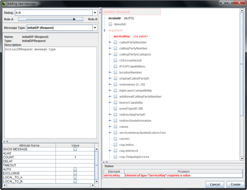
Select Add Message from the Edit menu, or click Add Message on the toolbar, or drag between roles lines where a dialog already exists. The Adding a New Message… dialog box displays.
|
||||||||
|---|---|---|---|---|---|---|---|---|---|
2 |
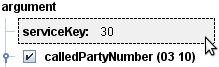
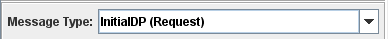
Select a Dialog and a Message Type (application context) from the drop-down lists, optionally fill out message content.
|
||||||||
3 |
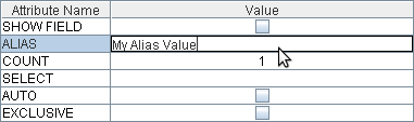
To specify message field values (for fields that take values):
|
||||||||
4 |
To specify message attributes:
|
||||||||
5 |
Click Create. The message displays in the body of the Scenario Editor.
|
| |
Editing and deleting messages
|
Message Editor Interface
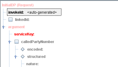
As shown in Adding and Editing Messages, the Scenario Editor uses a Message Editor interface for adding and editing messages. It consists of information about a message’s dialog and type, a tree of its elements, description and attributes of the selected element, and status of all elements.
DialogDropdown menu of available dialogs.
|
|
||
|
|
|||
|
|
|||
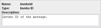
DescriptionDescription of the element selected in the message tree. |
|
||
AttributesTable of attributes for the element selected in the message tree.
|
|
||
|
|
Optional and Translatable Fields
Optional fields
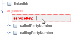
Message fields may be optional, which means they can be present or absent in a sent or received message. Standard optional fields have a square checkbox icon to the left of their field name: 
Choice fields
Some optional fields, known as choice fields, allow at most one mandatory choice from any set of choices. These fields have round (instead of square) icons: 
Field states
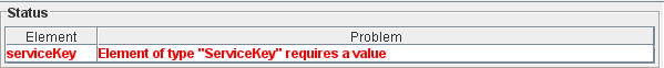
The state of an optional field determines its COUNT in the scenario definition, whether to include it when sending messages, and how it affects whether to match a scenario in received messages. The following table shows icon settings and their field’s corresponding COUNT in the scenario definition, whether the Simulator will include the field in that state when sending messages, and whether the Simulator will match the scenario for the field in that state when receiving messages.
| Icons | Setting | Count | Send | Receive | ||||
|---|---|---|---|---|---|---|---|---|
|
|
Mandatory |
1 |
Include. |
Only match if present. |
||||
|
|
Prohibited |
0 |
Do not include. |
Only match if not present. |
||||
|
|
Optional |
0..1 |
Do not include. |
Match if present; otherwise ignore. |
||||
|
(x..y) |
Non-standard COUNT |
|
||||||
|
|
Absent |
Empty icons represent fields which are not present in the scenario definition at all. |
||||||


| |
Mandatory is the default state for new fields. |
| |
Click the icon to change between states. |
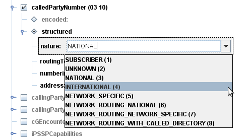
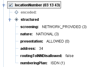
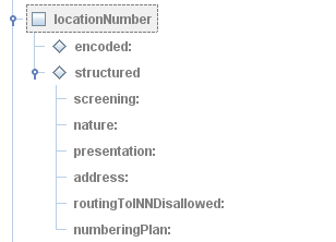
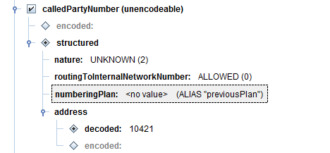
Translatable fields
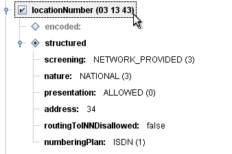
Translatable fields provide different views of the same raw data. Selecting them will translate the data into the selected view. For a scenario to be valid, one (and one only) of the available translatable fields must be selected, by clicking the diamond icon to the left of the field name: 
| |
Usually a translatable field has an 'encoded' form and one or more 'structured' forms. |
| |
The selected translatable field for a scenario definition has a filled icon:  |
Message Display Attributes
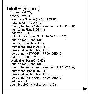
Two message attributes, SHOW MESSAGE and SHOW FIELD, are specific to the Scenario Editor. They are for display only, and do not in any way affect how the Scenario Simulator interprets a scenario.
Attribute |
|
|
||||
|---|---|---|---|---|---|---|
Where it appears |
On the root message element (such as |
On non-root message elements only. |
||||
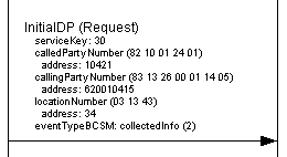
What it does if set |
Displays all message fields set in the Call Flow Editor. |
Displays the selected message element in the Call Flow Editor. |
||||
Example |
|
|
Adding and Deleting Fields
Below are instructions for adding fields, and deleting fields or just field data.
Adding fields
Multiple copies of the same field can exist in some messages. Such fields (for example, array field entries) have the +Add "fieldname" label associated with their parent elements.
| |
To add copies of a field, click its
|
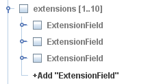
Like all other greyed out fields, these newly created copies just exist for display and editing — the Scenario Editor does not make them part of an edited scenario until you select or enter data in them.
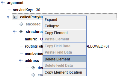
Deleting field elements
To delete one or more field nodes, select them and press the Delete key.
|
|
|
|

The Scenario Editor removes those fields — and all of their child fields — and any data they contain. For example, selecting the root node of a message and then pressing Delete will delete all data contained in the entire message.
| |
|
| |
The editor will always display at least one copy of a field, even if it contains no data. This is to allow exploration of the message structure without requiring new fields to be added manually. |
Deleting field data
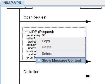
To delete the content of a field (as opposed to the field itself), select a field, right click, and select Delete Field Data from the context menu:
|
|
|
|
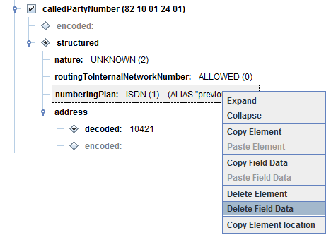
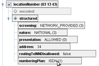
In the above example, the ISDN value is deleted while leaving all attributes and other properties of the field untouched.
| |
Deleting field content can cause validation errors due to missing data, because most fields do not support 'no value'. But deleting field data can be useful for fields populated by the alias or select attributes. |
Tips & Tricks
While adding or editing scenarios, you can:
| |
copy and paste callflow and message data |
| |
export dialogs to image files |
| |
zoom and scroll around the Callflow Editor |
| |
quickly select multiple callflow or message elements |
| |
undo and redo changes |
| |
use right-click shortcuts. |
Copying and Pasting
The Scenario Editor supports copy (Ctrl+C) and paste (Ctrl+V) at both the callflow and message-editing levels.
| |
You can also copy and paste using the right-click context menu in the Message Editor. |
Below are instructions for copying and pasting callflows, messages, message field data, and message field location.
Callflows
While editing a scenario callflow, you can copy and paste elements such as roles, dialogs, and messages. What gets pasted depends on what’s selected:
| With this selected… | This gets pasted.. | Notes | ||||
|---|---|---|---|---|---|---|
|
a single dialog |
messages only, into that dialog. |
|
||||
|
no dialog selected |
all copied scenario elements, into the currently selected scenario. |
|
Messages
While editing a message, you can copy and paste individual tree nodes --- and their children. For example, selecting a CallingPartyNumber and pressing Ctrl+C copies the entire CallingPartyNumber to the clipboard. You can then paste this data into another message (or the same message elsewhere), by selecting a destination CallingPartyNumber and pressing Ctrl+V.
| |
Pasting overrides the target data. In the example above, if the target had any CallingPartyNumber data, the Scenario Editor would replace it with the data from the clipboard. |
| |
Paste operations can result in illegal message structure. It is possible to paste the CallingPartyNumber in a place where it is inappropriate (such as pasting an ETSI INAP LocationNumber into a CallingPartyNumber. This can create illegal field elements that prevent the scenario from validating. |
| |
You can also copy a field element using the right-click context menu: 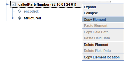 |
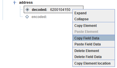
Message field data
To copy the field data (contents) instead of the field itself, right-click a field node and select Copy Field Data:
Copying message field location
To copy a description of the location of a field into the clipboard, right-click a field node and select Copy element location:
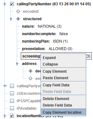
The example above copies this to the clipboard:
[InitialDPRequest -> [1] argument -> [2] callingPartyNumber -> [0] structured -> [4] screening{noformat[
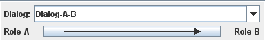
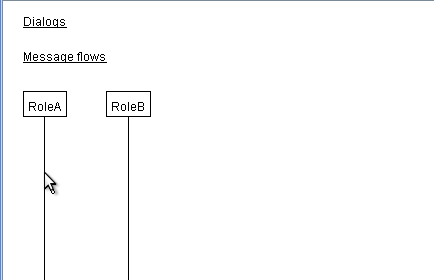
Dragging New Dialogs
When editing the message callflows, you can quickly create dialogs — between roles without an existing dialog — by dragging an arrow from one to the other:
-
Click and hold the mouse button on the line representing one role.
-
Drag and release the mouse button on the target role.
|
|
|
|

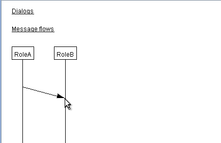
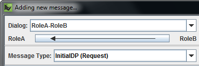
The Adding new dialog… dialog box displays for you to select the protocol and application context.
|
|
|
|
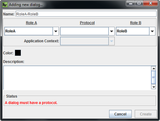
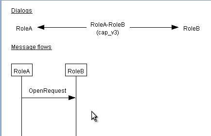
The example above shows the creation of a new dialog between RoleA and RoleB.
| |
This method of dialog creation has the added benefit of not requiring you to manually fill out the roles or dialog name — the Scenario Editor automatically names them to match the roles you drag between. |
| |
If a dialog already exists between those two roles, a New Message dialog box displays instead. |
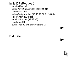
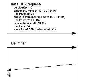
Dragging New Messages
When editing message callflows, you can quickly create messages — between roles which have an existing dialog — by dragging an arrow from one to the other:
-
Click and hold the mouse button on the line representing one role.
-
Drag and release the mouse button on the target role.
|
|
|
|
The Adding new message… dialog box displays for you to select the protocol and application context.
|
|
|
|
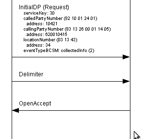
The example above shows the creation of a new OpenAccept on an already existing dialog.
| |
This method of message creation has the added benefit of not requiring you to manually select the dialog or send direction — the Scenario Editor automatically determines them by the roles you click and the direction you drag. |
| |
If a dialog does not already exists between those two roles, a New Dialog dialog box displays instead. |
Exporting Dialogs to Image Files
You can export the current scenario to an image (.PNG) file, to use elsewhere:
-
Select Export to PNG from the File menu.
The exported image file looks exactly like the on-screen representation (including any current selection and validation error coloring).
Navigating the Callflow Editor
Zoom
To zoom in and out of the main Callflow Editor display, use:
-
menu options — Zoom options in the Edit menu
-
shortcut keys — (Ctrl + +) to zoom in, (Ctrl + -) to zoom out
-
mouse movements - Ctrl + mousewheel up or down to zoom in and out.
To reset the zoom level to the default, using the Reset Zoom option from the Edit menu, or press (Ctrl + 0).
|
|
|
|
Selecting Multiple Elements
You can use the Shift and Ctrl keys, and click and drag, to select multiple callflow and message elements.
Callflow elements
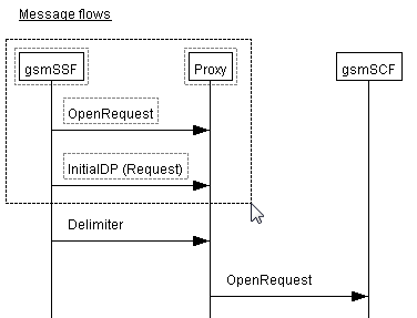
You can hold down the Shift and Ctrl keys while clicking, or click and drag to select multiple callflow elements. The following examples start with just the gsmSSF role selected in this scenario:
| To… | Do this | Example |
|---|---|---|
|
…add (or remove) an individual role, dialog, or message to (or from) the selection |
Ctrl-click. |
|
|
…select a role, dialog, or message — and all elements associated with it |
Shift-click. |
|
|
…add a role, dialog, or message — and all elements associated with it — to the selection |
Ctrl-Shift-click. |
|
|
…select multiple elements |
drag a selection lasso around them. |
|
Undoing and Redoing Changes
The Scenario Editor supports the undo (Ctrl+Z) and redo (Ctrl+R) edit operations. Each scenario and message edit have separate undo histories.
| |
When editing messages, only changes to the message elements are undoable — so changes to the message dialog or send direction cannot be undone. Also, making any changes to the scenario after performing one or more undo operations will discard any redo history that exists. |
Using the Callflow Context Menu
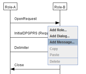
The Callflow Editor has right-click context menu support to copy and delete all components. You can also create messages, roles, and dialogs by right-clicking outside any component:
Using the Tools
The Scenario Editor comes with a few tools (available from the Tools menu) for reviewing protocol and scenario information. See:
Using the Schema Browser
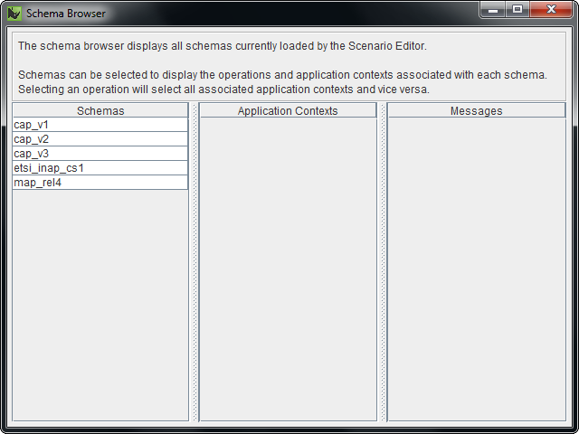
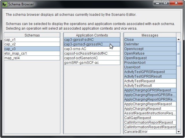
The Schema Browser lets you review protocol schemas currently loaded in the Scenario Editor.
1 |
To open the Schema Browser, select Schema Browser from the Tools menu. The Schema Browser displays.
|
||
|---|---|---|---|
2 |
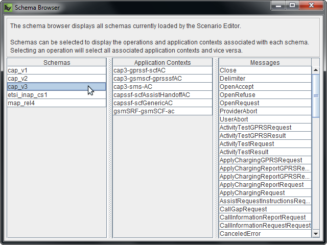
Click to select a schema. The Application Contexts and Messages for that schema display.
|
||
3 |
To view messages for one or more application contexts, click to select the application contexts. The Schema Browser highlights all messages that can be sent on those application contexts.
|
||
4 |
To view application contexts for one or more operations, click to select the operations. The Schema Browser highlights all application context that can be used for those operations. |
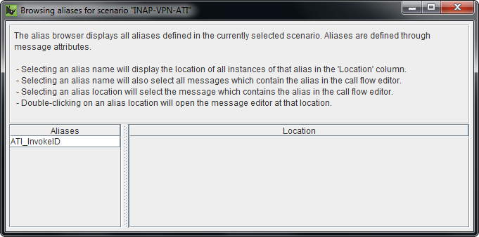
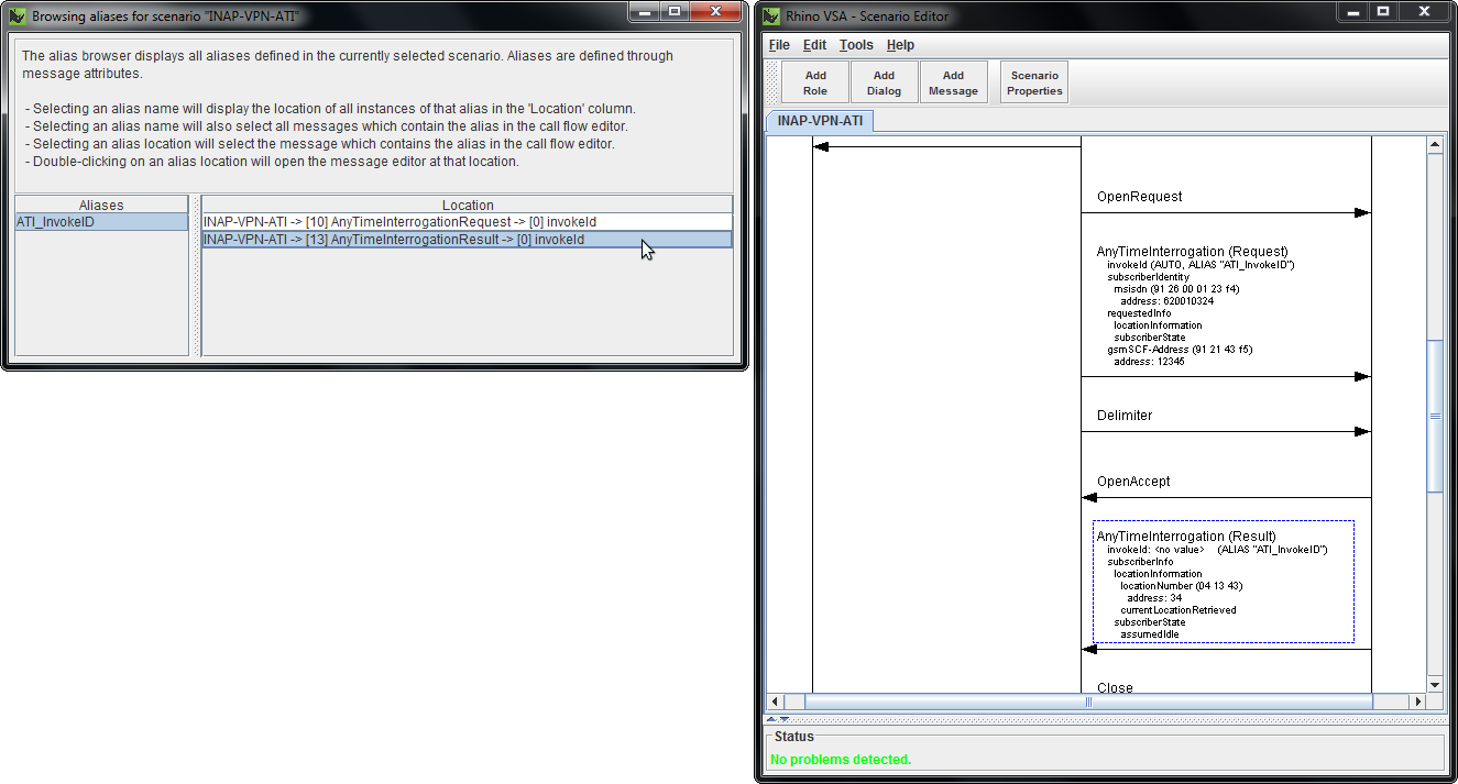
Using the Alias Browser
The Alias Browser lets you view all aliases in the currently open scenario.
1 |
To open the Alias Browser, select Alias Browser from the Tools menu. The Alias Browser displays.
|
||
|---|---|---|---|
2 |
Click to select an alias. Message fields associated with that alias display.
|
||
3 |
To select the message associated with an alias, click the alias in the Location column.
|

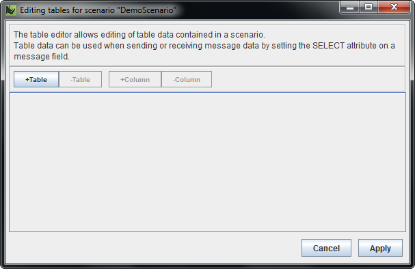
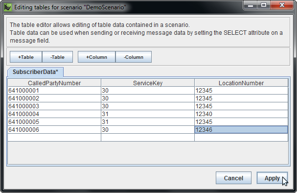
Using the Table Editor
Tables are an optional scenario mechanism for storing lists of related information that the Scenario Simulator uses for generation and matching logic.
| |
For more about how to use tables in a scenario (with the SELECT attribute on message fields), see the Scenario Simulator User Guide. |
1 |
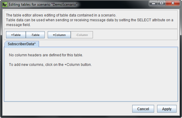
To open the Table Editor, select Table Editor from the Tools menu. The Table Editor displays.
|
||||
|---|---|---|---|---|---|
2 |
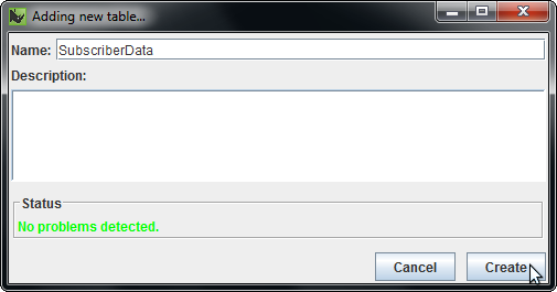
To create a new table, click Table. The Adding new table… dialog box displays.
|
||||
3 |
Enter a Name and (optionally) a Description for the table, and click Create. The new table displays in the Table Editor.
|
||||
4 |
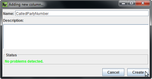
To create a new column for the table, click Column. The Adding new column… dialog box displays.
|
||||
5 |
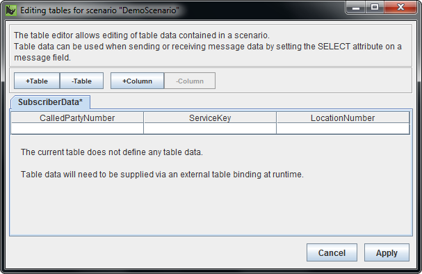
Enter a Name and (optionally) a Description for the column, and click Create. The new column displays in the Table Editor.
|
||||
6 |
Enter table data, and click Apply. The Table Editor automatically adds new rows when you enter data in a table cell, and removes empty rows at the end of the table.
|
Appendix A: Troubleshooting
| |
Resolving issues
This (hopefully small) section is intended to document common problems you may find using the Scenario Editor, and how to resolve them. Please use the OpenCloud forums to post any undocumented issues you encounter (or anything else you think belongs in this User Guide!). |
| Issue | Solution |
|---|---|
|
Everything is slow! |
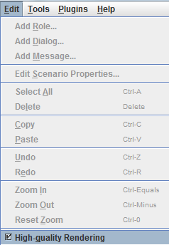
High-quality rendering is enabled by default in the Scenario Editor. On some configurations of hardware and software this can result in unacceptably slow performance. The problem can also occur when running the editor over a remote X connection. To resolve this, uncheck the High-quality rendering option from the Edit menu:
|