This document provides an overview of the CGIN connectivity pack.
Topics
|
What the CGIN connectivity pack is, and the case for 'CGIN' technology. |
|
|
An overview of the elements of the CGIN connectivity pack: and how they releate to each other. |
|
|
A description of the CGIN Unified Resource Adaptor, with an introduction to its APIs. |
|
|
A brief introduction to the technology used to build the CGIN connectivity pack (the CGIN tool chain), how protocol engineers can use it to build support for protocols, and software engineers use the generated results. |
Other documentation for CGIN can be found on the CGIN product page.
Introducing the CGIN Connectivity Pack
The CGIN (Computer Generated Intelligent Network) Connectivity Pack integrates the Rhino platform with SS7 networks and supports functional and load testing of SS7-based applications.
CGIN supports both industry standard and vendor-variant SS7 protocols. CGIN also includes tools to support functional and load testing of SS7-based applications.
| |
For more information about the CGIN connectivity pack read:
|
Why CGIN?
CGIN solves a number of challenges:
-
We need to support vendor variants of standard protocols.
-
We need to rapidly address integration issues with new equipment, because not all implementations of the standards are truly equal.
-
We need to support partners who wished to choose the SS7 stack or indeed had their own SS7 stack.
We use compiler-design and code-generation techniques to take protocol descriptions in ASN.1, and auto-generate not only the TCAP library, but the entire set of resource adaptor and associated metadata that a suite of tools needs for functional and load testing.
Inside the CGIN Connectivity Pack
The CGIN Connectivity Pack is OpenCloud’s product for integrating the Rhino platform with SS7 networks and supporting functional and load testing of SS7-based applications.
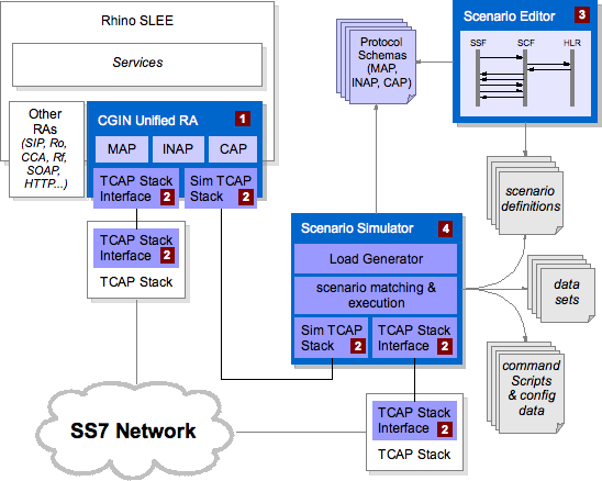
It includes:
Available as a separate download, the Scenario Simulator can be used with CGIN for scenario testing. It includes:
![]() If you are interested in evaluating CGIN download the latest CGIN Software Developers Evaluation Kit.
If you are interested in evaluating CGIN download the latest CGIN Software Developers Evaluation Kit.
Unified Resource Adaptor
The Unified Resource Adaptor supports multiple SS7 protocols with a pluggable architecture.
It includes a number of TCAP based protocol libraries (INAP, CAP and MAP in the diagram below) that run on top of a TCAP stack.
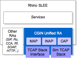
The Unified RA:
-
can load multiple ASN.1 based protocols inside it
-
can be configured to load a subset of the defined protocols (for example, only MAP)
-
supports ETSI INAP CS1, CAP v1, v2, v3, v4, and MAP:
-
ETSI INAP CS1 (ETS 300 374-1: September 1994)
-
CAP v.1 (ETSI TS 101 046 / GSM 09.78 V5.7.0 Release 1996)
-
CAP v.2 (ETSI TS 101 046 / GSM 09.78 V7.1.0 Release 1998)
-
CAP v.3 (3GPP TS 29.078 V4.8.0 Release 4)
-
CAP v.4 (3GPP TS 29.078 v9.1.1 Release 9)
-
Mobile Application Part (MAP) (3GPP TS 29.002 v10.0.0 Release 10)
-
-
integrates with an SS7 stack at the TCAP layer (ANSI and ITU TCAP are supported)
-
connects at the TCAP layer to either a real TCAP stack or a simulated TCAP stack.
TCAP Stack Interfaces
The Unified RA and the Scenario Simulator support TCAP in two ways, integrating with:
-
a simulated TCAP stack: a Java TCAP stack that simulates most of the behaviour of a real stack — but only connects to other simulated TCAP stacks — to support development and testing without requiring a real SS7 network
-
real TCAP stack interfaces:
-
OpenCloud’s OCSS7 TCAP stack,
-
Mavenir’s Signalware TCAP stack
-
Simulated TCAP stack
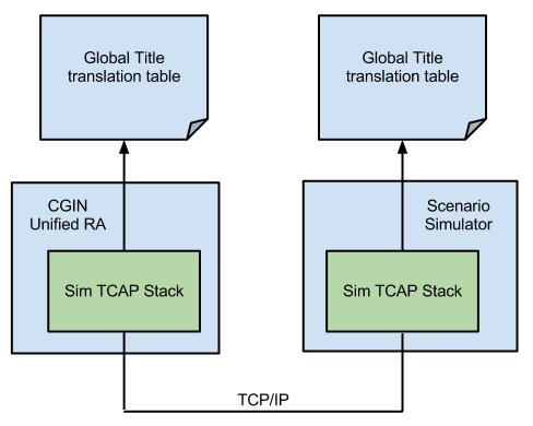
The sim TCAP stack simulates most of the behaviour of a real SS7 network. It is embedded in both the Unified Resource Adaptor and the Scenario Simulator, and can be used for testing without the need for a real TCAP stack.
| |
The sim TCAP stack is ideal to augment your testing capabilities. However it is not a substitute for testing on a real network. |
Each TCAP simulator (in the Unified Resource Adaptor entity and CGIN Scenario Simulator) connects to other TCAP simulator instances directly using SUA over a proprietary TCP-based protocol. Each TCAP simulator uses SUA dynamic routing configuration to discover its routing configuration, plus each has its own global title translation table.
| |
|
OCSS7 TCAP Stack
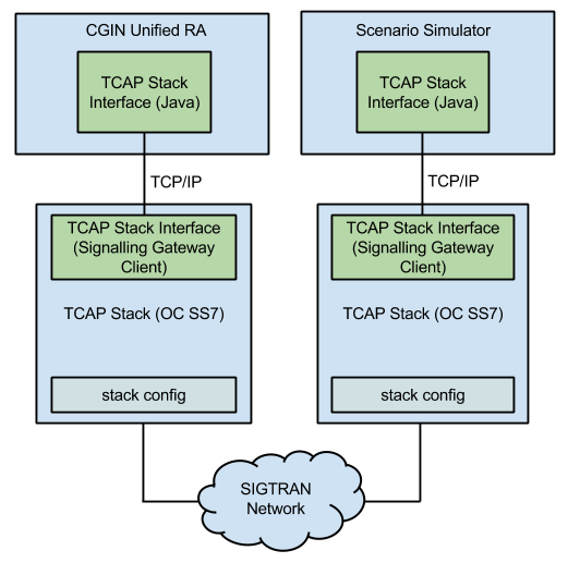
The Unified Resource Adaptor and the Scenario Simulator both integrate with the OCSS7 TCAP stack with:
-
a Java component that is embedded in the CGIN Unified RA and Scenario Editor
-
a signalling gateway client.
These two components communicate through a proprietary TCP/IP-based protocol.
| |
For more information about the OCSS7 TCAP stack, please see Using the OCSS7 TCAP Stack. |
Signalware TCAP Stack
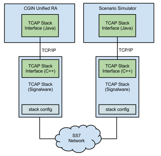
The Unified Resource Adaptor and the Scenario Simulator both integrate with the Mavenir Signalware TCAP stack with:
-
a Java component that is embedded in the CGIN Unified RA and Scenario Editor
-
a C++ component that executes in the Signalware environment.
These two components communicate through a proprietary TCP/IP-based protocol.
| |
See Using the Mavenir Signalware TCAP Stack for more details about configuring the Signalware TCAP stack. |
Scenario Editor
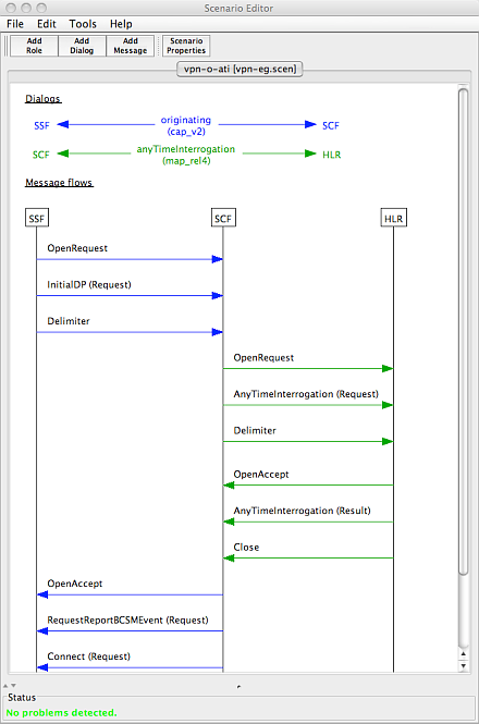
The Scenario Editor is a visual tool for building call flow scenarios for use with the Scenario Simulator.
The screenshot to the right shows the Scenario Editor in action scripting an originating call scenario for a VPN-style application that is querying the HLR for location information of the called party.
The Scenario Editor is parameterised by protocol schema libraries that encode the rules of the protocol, such as the Application Context Names (ACNs) available, the operations and responses supported by each ACN, and so on.
You use the Scenario Editor to:
-
Define network roles and dialogs for use in a signaling scenario.
-
Create operation call flows including request, response, and error operations.
-
Define the parameters of each operation. You simply choose the parameters to include, fill in fields and select values from pull-down lists.
-
Explore protocols with the built-in schema browser. For example you can browse the ACNs to see what operations and responses are supported, or you can choose an operation/response and see which ACNs use it.
-
Edit multiple scenarios at the same time, and easily copy data between them.
-
Visually display and correct problems with a scenario before running it in the Scenario Simulator. The Scenario Editor monitors your progress and provides constant feedback about the conformance of your scenario to the requirements of the protocols used.
-
Export scenarios to an image file for use in presentations or documentation.
| |
Read the Scenario Editor User Guide for more details about creating signalling use cases with the Scenario Editor. |
Scenario Simulator
The Scenario Simulator is a very powerful and flexible testing tool for simulating traffic in SS7 networks.
Each supported SS7 protocol is specified by a protocol schema. A protocol schema defines the types of messages and fields which are valid for a particular protocol.
You can use the scenario simulator to generate traffic (for example, to emulate an SSF) or to receive traffic (for example, to emulate an SCP or HLR) for functional and load testing. Imagine, for instance, you are working on a VPN-style application. You can write scenario definitions covering all the ways your application can interact with the switch, and also all the ways your application can interact with an HLR. The Scenario Simulator incorporates powerful scenario-matching technology and applies the most appropriate scenario based on the messages sent and received.
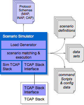
You use the scenario simulator for testing network elements and services by building a test environment with:
-
test cases defined as scenario definitions — Each scenario definition (defined with the Scenario Editor) describes the end-to-end message flow for a particular call-flow use case. The Scenario Simulator can simulate many scenarios at the same time.
-
test data as data-sets — Tables of data used in scenario definitions during runtime. Data-sets can either be specified inline (inside the scenario), or in an external CSV file.
-
endpoints — You can configure physical network endpoints with an associated address. Endpoints are bound to roles that are defined in the scenario definitions. The endpoints are part of the configuration data.
-
a TCAP stack — You configure the simulator to connect with an external TCAP stack or to use the built-in sim TCAP stack
| |
Read the Scenario Simulator User Guide for more details about generating traffic with the Scenario Simulator for functional and load testing. |
CGIN Unified RA
In this section we explore the CGIN-based support for SS7.
CGIN approach to SS7 APIs and resource adaptors

-
One resource adaptor for all TCAP user protocols
-
Resource adaptor APIs, resource adaptor types, and resource adaptor implementation are auto-generated by the CGIN toolchain
-
Integration with underlying SS7/SIGTRAN implementations is at the TCAP layer.
-
Any protocol with an ASN.1 definition is supported by the CGIN toolchain. For example, vendor variants and customisations of standard protocols can be supported.
The following section explores the CGIN Resource Adaptor APIs.
Resource Adaptor APIs
This page presents the CGIN family of APIs.
CGIN family of APIs
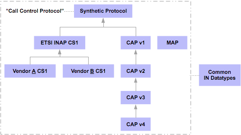
CGIN provides a suite of APIs for INAP, CAP, and MAP. The diagram below shows the set of APIs provided in the CGIN Connectivity Pack.
Call control protocol APIs are defined as a hierarchy where each protocol API is defined as an extension of another protocol API. For example CAP v4 extends CAP v3, which extends CAP v2, which extends CAP v1.
At the root of the hierarchy is the CGIN Call Control (CGIN CC) API. CGIN CC is a synthetic call control protocol that is the intersection of ETSI INAP CS1 and CAP v4. Call control applications can be written in terms of the CGIN CC API and may be largely independent of the actual signaling protocols used.
| |
The CGIN Call Control API is also generated by the CGIN toolchain. CGIN CC has its own ASN.1 description, which is why we refer to it as a synthetic protocol. |
-
Call Control API — API for the synthetic protocol that is the intersection of INAP and CAP.
-
INAP APIs — A family of INAP APIs that are based on a common definition of ETSI INAP CS1
-
ETSI INAP CS1 (ETS 300 374-1: September 1994)
-
Please contact Metaswitch for information pertaining to INAP variants supported
-
-
CAP APIs — A family of CAP APIs that are based on the definition of CAP v1
-
CAP v.1 (ETSI TS 101 046 / GSM 09.78 V5.7.0 Release 1996)
-
CAP v.2 (ETSI TS 101 046 / GSM 09.78 V7.1.0 Release 1998)
-
CAP v.3 (3GPP TS 29.078 V4.8.0 Release 4)
-
CAP v.4 (3GPP TS 29.078 v9.1.1 Release 9)
-
-
MAP API — An API for GSM MAP.
-
Mobile Application Part (MAP) (3GPP TS 29.002 v10.0.0 Release 10)
-
-
IN Datatypes API — A library of classes to represent types for which their ASN.1 specification is
OCTET STRING, and for which standards define the layout of bit-fields within the octet string (for exampleCalledPartyNumberandISDNSubaddress). -
X.S0004 API — An API for X.S0004-E/CDMA. Please contact Metaswitch for X.S0004/CDMA support.
| |
Learn more…
See: CGIN APIs for javadoc of all APIs in the CGIN family. |
CGIN APIs
The CGIN APIs represent an SS7 message as a POJO (Plain Old Java Object). This SS7 message POJO is only responsible for encapsulating the fields of the SS7 message it represents. Applications can therefore safely store messages in CMP fields.
The CGIN CC InitialDP, for example, is represented by the CCInitialDPArg class.
// A POJO that represents an InitialDP
public class CCInitialDPArg extends AbstractFieldsObject {

    public CalledPartyNumber getCalledPartyNumber()   { ... }
    public CallingPartyNumber getCallingPartyNumber() { ... }

    // + other methods for accessing fields of the InitialDP
}
SLEE events are represented as a separate class with an associated message POJO.
The CGIN CC InitialDP request, for example, is shown below. The CCInitialDPRequestEvent extends from the OperationInvokeEvent generic class, with a type parameter value of CCInitialDPArg. CCInitialDPArg is the POJO class that represents the InitialDP message itself.
/**
* Base class for all operation-specific invoke event classes.
* Individual protocols subclass this event for each operation they support.
* Each operation defines its own event type.
*/
public class OperationInvokeEvent<ArgType> extends OperationEvent {

    public ArgType getArgument() { return argument; }

    // ...
}

// ...

public class CCInitialDPRequestEvent extends OperationInvokeEvent<CCInitialDPArg> {

    // ...

}| |
Restrictions imposed by the SLEE programming model
The SLEE programming model imposes some restrictions on what a SLEE application can do with an event. An important one that programmers often misunderstand (or simply forget!) is that event objects should not be stored by the service in CMPs (or by using any other method) for use in future transactions. This is simply because the event is owned by the resource adaptor and the SLEE has no knowledge of how the event object has been implemented (and therefore cannot make any assumptions in terms of persistence and so on). |
Event Models
CGIN 2.0.x supports two service event models:
-
A message oriented event model, introduced in CGIN 2.0.0.
-
A component oriented event model, the sole model prior to CGIN 2.0.0.
Under the component oriented event model a received TC-BEGIN would look like the following (numbered flows are events received by the service):
  (1) --> OpenRequest components=[Invoke]
  (2) --> OperationInvoke (subclass)
  (3) --> Delimiter
Under the message oriented event model the same flow would look like:
(1) --> DialogMessage.BEGIN components=[Invoke]Similarly, a received TC-END in direct response to a TC-BEGIN sent would look like this under the component oriented model:
  (4) --> OpenAccept
  (5) --> OperationResult
  (6) --> Close
  (7) --> ActivityEndEvent
Under the message oriented event model the same flow looks like:
  (2) --> DialogMessage.END components=[Result]
  (3) --> ActivityEndEvent
The benefits of the new model are two-fold:
-
Less events.
-
The whole network message may be inspected easily (for example, determine if it’s a TC-CONTINUE or TC-END without having to wait for the Delimiter or Close event), which can simplify service logic in some cases.
Using the Message Oriented Event Model
In order to use the message oriented event model, services should:
-
Have event handlers for BEGIN/CONTINUE/END as required.
-
Additional handlers may be needed for OperationInvokeTimeout, UserAbort, ProviderAbort and OpenRefuse as with the component oriented event model.
-
Any initial event selector should expect a DialogMessageEvent instead of OpenRequestEvent.
See DialogMessageEvent in the CGIN APIs for further information.
Converting Existing Services to the Message Oriented Event Model
Existing services may be adapted to use the message oriented API without needing a complete rewrite. This is a quick overview of that process:
-
Create new event handlers for BEGIN/CONTINUE/END and OperationInvokeTimeout.
-
Remove the declarations for the old event handlers (sbb-jar or annotations).
-
Convert the initial event selector for OpenRequestEvent to expect a DialogMessageEvent instead.
-
In the new event handlers, iterate over the components of the DialogMessageEvent and delegate to the old event handlers as appropriate.
-
If the service cares about Delimiter or Close, synthesize calls to those event handlers after processing components, based on DialogMessageEvent.getMessageType().isLastMessage()
-
User abort, provider abort and open refuse handlers are unchanged.
-
OperationInvokeTimeout should be delegated to the provider error handler. If necessary, synthesize a Delimiter event handler call afterwards.
CGIN Tool Chain
CGIN (Code-Generated IN) is a suite of tools, libraries, and frameworks from OpenCloud that we use to build SS7 resource adaptors and tools for the Rhino platform.
The CGIN tool chain supports a build process for generating:
-
protocol APIs that developers use to build applications on the Rhino platform
-
protocol libraries that plug into the CGIN Unified Resource Adaptor
-
protocol schema definitions that plug into the Scenario Editor and the Scenario Simulator.
The outputs of the CGIN tool chain are collected into the CGIN Connectivity Pack.
Building support for protocols and using the generated results
The following diagram shows an overview of the CGIN tool chain in relation to protocol engineers who are building support for protocols, and software engineers who use the generated results.

1 Prepare input …
Input to the CGIN process includes:
-
ASN.1 protocol definitions — The ASN.1 defines the Application Contexts (ACs) defined by the protocol; all the requests, responses, and errors possible for those ACs; as well as the parameters of these messages.
-
Protocol and API adaptations — Protocol engineers can script custom adaptations of the protocol using the OpenCloud adaptation Domain Specific Language (DSL). For example a protocol engineer can: exploit existing handwritten types by mapping them to ASN.1 types, interpret data contained within plain
OCTET STRINGs, define how the protocol fits into the OpenCloud call-control API hierarchy, and so on.
2 Execute the CGIN tool chain …
The CGIN tool chain is then used by protocol engineers to transform the ASN.1 and adaptation definition into:
-
an API and corresponding SLEE resource adaptor type — so software engineers can write SLEE-based applications that use the protocol
-
documentation of the API in the form of Javadoc — to make the software engineers' job easier as they write their applications
-
Java components that plug into the OpenCloud Unified Resource Adaptor — so software engineers can run their applications on the Rhino platform
-
a protocol schema definition — so software engineers can write scenario definitions (signaling use cases) for the protocol, using the Scenario Editor, to use with the Scenario Simulator for functional and load testing.


